View factors : create a differential surface from CAD file

Hello,

I’m a total newbie to radiance. My goal here is to calculate the view factor between the outer surface a sensor (a radiometric cavity) and its immediate environment (the radiation shield and front aperture surrounding it) in order to later calculate the impact of the radiative exchange on the thermal equilibrium of the sensor in question.
I think I have understood how to convert the different shapes from .obj files exported by my CAD software to .rad files, attribute them different materials to make sure to calculate the view factor from one piece to another, with anything else acting as an obstruction and then, build the octree representing the scene.

Now I understand that -rcontrib is used to calculate the view factor between a (series of) differential surface(s) and another surface; which means that I must turn the radiometer into a set of differential surfaces (cloud of “oriented” points - list of x y z vx vy vz). Is there a way to easily do that ? A format to export your CAD file into, or a plug-in ? A tutorial to guide me to ? I welcome any help.

Thanks in advance
Julien

Hi Julien,

Welcome to the forum. You are asking an advanced question out of the gate, so the answer I’m about to give might be confusing. It might even be wrong, or at least wrong for your purpose, which I don’t fully understand.

It seems the tool that could be most useful is rfluxmtx, which is a kind of front-end to rcontrib. If you give it a set of “receiver” surfaces, it can generate a matrix of coefficients between some angular sampling of each receiver, which may be “u” for “uniform” in your case, and a single sender surface, also with a possible angular sampling. The rfluxmtx tool does the sample generation over receiver surfaces for you, simplifying the problem.

If you can describe your situation more completely, maybe include a JPEG figure or the like, I might be more helpful.

Best,
-Greg

Hi Greg,
Thank you for your answer. To describe the situation more completely, I’m a physicist specialised in sunlight irradiance measurements : these measurements are mostly done via “electrical substitution radiometers” : a black cavity kept at a steady temperature by means of electrical heating with a servo (a thermostat if you prefer), it’s geometry and coating make sure almost no light entering it escapes ; when light enters the cavity, it substitutes to part of the electrical heating and the difference in electrical heating needed to keep the temperature constant with or without light directly gives how much optical power, and thus irradiance, entered the cavity.

This supposes of course that the only parameters that change in the thermal equilibrium of the cavity are the incoming of (sun)light or not, and the electrical heating power, and that the heat exchanged between the cavity and its immediate surounding, by conduction or by radiation, is at least constant. This is typically achieved by surrounding the cavity by a “thermal shield” that is kept at a steady temperature by its own controlled electrical heating (usually a few degrees lower). That usually works perfectly well and we never have to try understanding the magnitude of the radiative and conductive heat exchanges between the cavity itself and its surrounding environment : they are constant and that’s all that matters.

Unfortunately, we launched a CubeSat (a small, cheap, test satellite with minimalistic design) three years ago, inequiped with a radiometer to measure the sun irradiance, and the heating wire supposed to keep the thermal shield of the radiometer was short-circuited, rendering it unusable. So we are able to measure the temperature of the shield surrounding the cavity , but we can’t keep it steady - the heating system of the cavity works like a charms and keeps its own temperature very steady on the other hand.

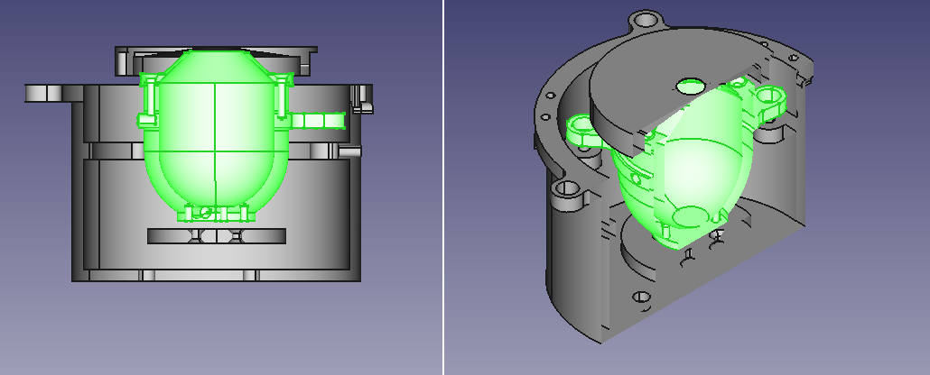
Now if we still want to be able to extract the incoming light from the data of the satellite, we have to evaluate how much heat is exchanged between the cavity and the shield surrounding it, which includes a radiative contribution, which demands that we know the viewfactor from the cavity to the shield (and also the precision apperture in front of the cavity that is a separete piece).

As you’ll see on the picture herewith, this is a bit more complex than cylinder to concentric cylinder, and our attemps for an analytic resolution failed (they resulted in non-physical results when we calculate the thermal equilibrium inside of the cavity). So what I’m trying to do now is to calculate the view factor between several pieces of the contraction (cavity to shield, cavity to apperture) that are at different temperature and each will have their own contributions to the thermal equilibrium of the cavity, whence my need to know the different view factors. These pieces have been modeled by the mechanical engineer of our team in .stp files that I have been able to convert them in .obj, and then to create .rad files for Radiance.

I discovered Radiance via several scientific publications that evaluated its ability to calculate the view factor via rcontrib and considered it better than radiosity based method when there are obstructions to take into account, but a scientific publication is not a tutorial. I do realise that what I’m asking is not a usual and probably an advanced question, but apparently, it’s doable, I’m just not entirely sure how it is to be done.

So, here is my more complete description of y situation. Sorry if it was long to read or too much information and I hope this helps clarify my question. In the meantime, I’ll read more in details about rfluxmtx.

Thanks again,
-Julien

Wow, Julien. Sounds like Real Science going on, here. I appreciate the complexity and difficulty of your challenge. It’s almost as if you want a set of evenly-spaced positions across your surface for form-factor calculation. The rfluxmtx is designed to compute flux transfer between hemispheres, so may not be suitable for this purpose after all.

The person who has the most experience with bending Radiance to do view-factor calculations is @sarith Perhaps you have read his (our) recent paper on the topic? My contributions were minor – he is definitely the brains on this one.

Is the temperature of your surrounding shield constant over its surface, or does that vary as well (or do you not have data)? If all you need is to know how much “shield” is visible from each point on the outside of your cavity, then it might just be a matter of counting ray intersections with rtrace. You would just need a method to generate randomly distributed rays from the outer cavity surfaces. I guess that’s the tricky part.

-Greg

Hi @JulAmd , this appears doable. As Greg mentioned, the tricky part might be to generate the rays on the cavity. However, here are a few open-source command line tools built around Radiance that could be leveraged for this purpose.
I think rcontrib is perhaps more suited for this task as we explained in the paper. I would have to look at your rad geometry file before I can propose anything definitive. If the actual geometry is not sharable, you can create a similar use-case and share that.

Regards,
Sarith

PS: Feel free to mail me sarith(at)rhrk(dot)uni-kl(dot)de in case you’d prefer to discuss this outside the forum.

Hi Julien,

If you are comfortable with Python, perhaps give frads a try. We have a function to calculate view factors that uses rfluxmtx on the backend.

Something like this might work:

import frads as fr

cavity_primitives = fr.unpack_primitives("cavity.rad")
shield_primitives = fr.unpack_primitives("shield.rad")
view_factors = fr.surfaces_view_factor(cavity_primitives, shield_primitives)
vf_cs = 0
for vfs in view_factors.values():
    vf_cs += sum(vfs.values())

Note that the cavity and shield surface normal should point inwards.

Hi @sarith , thank you for your answer. I have already read the paper that you and @Greg_Ward mention and it has been the most helpful source for my problem. This is precisely in generating the rays that I struggle.

I can share the design, we’re a public research institute and this is not our most secret bit of project ! You can find it on my public document carrier https://mail.meteo.be/home/[email protected]/Public/Radiance or on my own OneDrive : https://1drv.ms/u/s!Ai-U65tKi7UJiL5QBWjTOnu8LVFy-w?e=Cjem7s

Thanks again for the answer.
Julien

Hi Taoning,

That seems very interesting – do you use rfluxmtx on one sender surface at a time in your view factor calculation? I know that rfluxmtx normally finds an “average surface normal” for a collection of sender surfaces, which would tend to underestimate the view factor in this case. You must be doing something different.

-Greg

Yes, we assume the surface are already broken down into individual primitives and we just loop through each one. We also take into account the rest of the sender surfaces and flip the surface normal. When computing the view factor for one primitive, the “environment” is always the receiving surface plus the rest of the sender surfaces.

1 Like

Hi Taoning, I’m trying to implement your solution but I have two questions whose answers I can’t find in the doc :

  • How do you take obstructions into account, there are a two other pieces in my setup and some obstructions are gonna take place. Is there a way to import an octree that describes the whole scene ?
  • frads assumes that the surface is already broken down into primitives, says you. Based on what does it do that and more specifically, do I need to do it manually ?

Thank you for your contribution. My python is very basic but that’ll be a good excuse to lean a bit more into that language !

Julien

You need to include your obstruction inside your shield.rad. This means that you will calculate view factors to obstructions as well. You should name your identifiers properly so that you can easily separate them out later. For example, in your shield.rad file, you should have something like this (the material here doesn’t matter but we do need it):

void plastic mat1
0
0
5 .4 .4 .4 0 0

mat1 polygon shield1
0
0
 ...

mat1 polygon shield2
0
0
 ...

mat1 polygon obstruction1
0
0
 ...

In your cavity.rad file, you have something like this:

mat1 polygon cavity1
0
0
 ...

mat1 polygon cavity2
0
0
 ...

These individual polygons should corresponds to polygons in your CAD file and obj2rad should take care of that for you.

You resulting view_factors will be a dictionary like this:

{"cavity1":{"shield1":0.03, "shield2":0.05, "obstruction1":0.01...}, "cavity2": {"shield1":...}...}

You can then remove “obstruction” values by filtering the name:
{key: {k:v for k,v in val.items() if key.startswith("shield")} for key, val in view_factors.items()}

If your surface normals are not what need to be, their value will likely be zero.

Hopefully this helps.

Hi,
Thanks a lot for the help. Somehow executing the script above wouldn’t work : I’ve got an error “rfluxmtx: too many arguments!” accompanied by a runtime error. I’ve haven’t been able to find a solution by myself so I would be grateful if you have an idea of why this is and what to do.
I saw this topic from 2018 that said the number of polygons in rfluxmtx are limited but the limit can be increased, but after reading rfluxmtx source code, I see this has been increased as part of the standard radiance distribution, thus this mustn’t be the origin of the issue.

The exact message I get trying to execute your script is

$ python test.py 
/home/pathTo/pyradiance/bin/rfluxmtx: too many arguments!
Traceback (most recent call last):
  File "/home/pathTo/pyradiance/anci.py", line 22, in wrapper
    result = func(*args, **kwargs)
             ^^^^^^^^^^^^^^^^^^^^^
  File "/home/pathTo/pyradiance/util.py", line 702, in rfluxmtx
    return sp.run(cmd, check=True, stdout=sp.PIPE, input=rays).stdout
           ^^^^^^^^^^^^^^^^^^^^^^^^^^^^^^^^^^^^^^^^^^^^^^^^^^^
  File "/usr/lib/python3.11/subprocess.py", line 571, in run
    raise CalledProcessError(retcode, process.args,
subprocess.CalledProcessError: Command '['/home/pathTo/pyradiance/bin/rfluxmtx', '-c', '10000', '-n', '1', '-w', '-ffd', '/tmp/tmpwme95jxu/surface', '/tmp/tmpwme95jxu/receiver', '/tmp/tmpwme95jxu/scene']' returned non-zero exit status 1.

During handling of the above exception, another exception occurred:

Traceback (most recent call last):
  File "/home/pathToDoc/test.py", line 5, in <module>
    view_factors = fr.surfaces_view_factor(cavity_primitives, shield_primitives)
                   ^^^^^^^^^^^^^^^^^^^^^^^^^^^^^^^^^^^^^^^^^^^^^^^^^^^^^^^^^^^^^
  File "/home/pathTo/frads/matrix.py", line 819, in surfaces_view_factor
    mat.generate(params=["-c", f"{ray_count}"])
  File "/home/pathTo/frads/matrix.py", line 400, in generate
    matrix = pr.rfluxmtx(
             ^^^^^^^^^^^^
  File "/home/pathTo/pyradiance/anci.py", line 25, in wrapper
    raise RuntimeError(
RuntimeError: An error occurred with exit code 1: 

Can you post your script and files somewhere so that I can take a look? You can also send them to me at [email protected]

Hello,
Thanks for your fast reaction.
You can find the files and the script here : https://1drv.ms/f/s!Ai-U65tKi7UJiL8s1EGez-hANa5QkQ?e=ccZo74
The script is the one you wrote above with no modification. The file “cavity.rad” is the sender surface, the file “shield.rad” contains the receiver (shield) and obstructing bodies

I think you are hitting the MAXRCARG=10000 limit. For this calculation, each receiver surfaces expands to 6 arguments passing to rcontrib, which translates to 10000/6 ~= 1600 surfaces. You have ~1900 surfaces to calculate view factors.
We can either increase this limit( @Greg_Ward ?). Or you can check for surfaces that can be merged, reducing the number of receiver surfaces. For example, if you don’t care about the view factors to some of the obstructions, those geometry can be simplified?

Wow, I haven’t seen it that way, I thought it was 10000 polygons. I will see if I can also decrease the number of surfaces. I can rebuild my version Radiance the source-code and let you know if it worked.

Would I be able to build Radiance again by simple running ./makeall -install without uninstalling it first ?

If you alter any of the source files and re-run makeall, it should update with your changes. That said, there is an underlying system limit to the number of command-line arguments, and 10,000 isn’t far from it. You may not gain much by increasing MAXRCARG in other words. The -M option doesn’t have this limit, but I don’t know how that interacts with frads. You can also bypass the system limit by passing a file of arguments using “@argfile.txt” or similar.

Cheers,
-Greg

We are using rfluxmtx to handle the surfaces ray spawning. Don’t we have to use rcontrib to use the -M?
An alternative will be to run it in batches, which should be fine for view factor calc.

@JulAmd if you recompile, you’d need to place and overwrite rfluxmtx in pyradiance installation path, since pyradiance (and frads) use its own radiance. You can find your path by running import pyradiance; help(pyradiance) the path is at the bottom. You need to place rfluxmtx in the bin there.

Thank you very much for your input. Following your advice, I copied rfluxmtx into the pyradiance bin. The execution time was subsentially longer, meaning that something has changed, but it was interrupted by this error :
rcontrib: fatal - duplicate modifier 'rflxmat1HMNV9'
By any chance, do you know what it could be ?

I don’t know about the latest error. This seems to indicate that the same modifier is being repeated on the input.

There isn’t an easy solution to the issue with argument counts and rfluxmtx. As I mentioned, there is a hard limit at the system level to the number of arguments, which is usually 10240. It wouldn’t work to increase MAXRCARG past this, which won’t buy you much. Unfortunately, there is also no easy way to bypass this limit in rfluxmtx, due to the parsing of spaces in @file.txt arguments.

Partitioning the calculation up into manageable chunks as Taoning suggested may be the only way. Having so many modifiers isn’t very efficient in rcontrib in any case.

Best,
-Greg