Is it valid to average pixel daylight factor % across a .hdr image that has had pfilt x/2 y/2 applied to it? Or must the results be extracted from the source hdr before this transformation occurs?
It depends on what you are using to extract the daylight factors. In any case, if you use the pfilt -1 option and don’t use the -e option, you should get roughly the same values in the same parts of the image.
Hope this helps.
-Greg
Hi Greg,
Thanks for the swift response. I should have anticipated the It depends and give some more context.
See both hdr images here. LINK
These are the differences I am seeing in the results. I am using pvalue to extract the pixel values, perform conversion to gain daylight factor against a 10K lux sky.
Image 1 using rpict from IES that had pfilt x/2 y/2 applied.
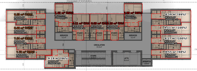
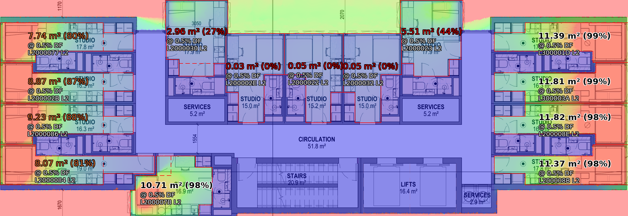
Image 2 run using rtpict on the same octree.
Are any of the below the cause of this difference:
- different versions of radiance used
- stochastic behaviour of rtpict versus rpict.
- It is a behaviour only seen at high -ab values.
- it is invalid to calculate daylight factor percentage based on an image that has had pfilt x/2 y/2 applied to it.
I don’t have the source file from IESVE to compare the pfilt image with this source. I don’t know where it is sent.
If you look at the header from the IES output picture using the Radiance getinfo tool, you’ll note that the pfilt command doesn’t use the “-1” option, and therefore does an exposure averaging and prints out an “EXPOSURE=” line to call attention to it:
	pfilt -x /2 -y /2
	EXPOSURE=1.102261e-001
This indicates that reported amounts should be about 1/9th of their original values. If you want to query the original quantities in the picture, simply use the pvalue “-o” option. Then, I think your values should align much better.
Cheers,
-Greg
P.S. Your rtpict run didn’t pass through pfilt or have its exposure changed, so its report with or without the pvalue -o option should be correct.
Hi Greg,
The pvalue -o option was used to produce the above results using the iesve.pic.
I have applied pfilt x/2 y/2 to the 527DP_plan_ffl_14300.hdr
The results above continue to agree with the image prior to this pfilt. The difference still stands between the IES image and my own image produced from the same octree.
Which brings me back to possible reasons for differences:
- different versions of radiance
- stochastic behaviour of rtpict versus rpict. Rpict uses -ps -pt -pj where rtpict doesnt. Should I test out changing ambient parameters (-aa -ar -as -ad) to higher values in rtpict run? or could cache contention at the N64 in the rtpict run cause larger variance in the output results?
- It is a behaviour only seen at high -ab values…
To convince my workplace to move to using rtpict on cloud VMs, these differences ring alarm bells with >5-10% difference, and I’m unsure what to test next if at all it is possible to attempt to explain the differences.
Thanks,
Vince
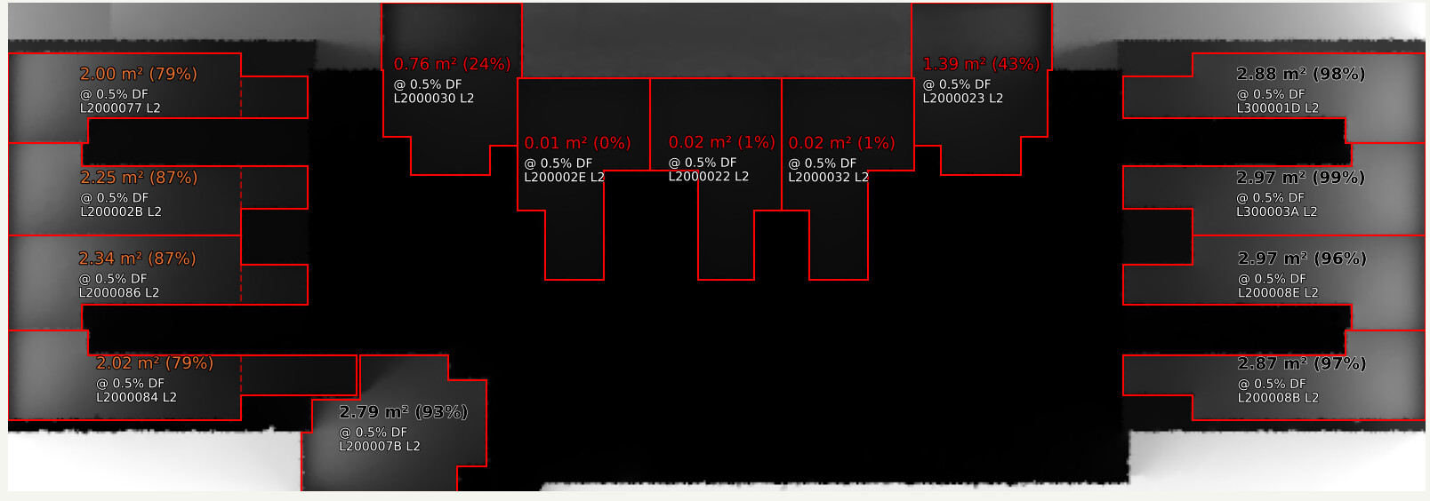
Sorry – I can’t really read any of the numbers on your included JPEG images, which is part of my problem. Computing the ratio of these two images, I see a lot more differences that could not have been caused by pfilt, but must be due to big differences in the calculations. It is confusing to say this is a “before” vs. “after” pfilt problem, when the differences must be in both “before” pictures.
The rpict -p* options are not the problem, either.
I would say there are some significant errors in the rtpict calculation judging by the artifacts. The IES calculation looks a lot cleaner to me, especially in the central office space. Since I don’t see anything standing out in the two sets of options, the -a* ones being most important, I also wonder if it might be a difference between the two versions. Your “RADIANCE 6.0a” doesn’t tell me a lot about which one you’re using, but I suggest the following:
- Remove the ambient file used in rtpict and re-run this command to see if the results are consistent.
- Download the latest HEAD release of Radiance from this link and repeat #1 to look for differences.
There have been so many changes since release 5.1a, this may take time to track down. If you don’t mind uploading your model, I might even have a go at it myself.
Cheers,
-Greg
Hi Greg,
I have uploaded the OCTREE, VIEW files and Area of interest files (i.e. the room boundaries seen in the images above)
Please see all attached here.
https://drive.google.com/drive/folders/1ffDn3okbOhnKb58aHTzNRG_ybCVLZ55m?usp=drive_link
Thanks, Vince.
I spent the last hour or two investigating, and it seems the older “5.1a” release being used by IES in this way is leading to inaccurate results as far as I can tell. The newer results are also not perfect since they show some spotty non-zero daylight factors in the middle where it should be totally black – there appear to be no doors or windows to let light into this space.
The exact source of the differences is hard to pin down, as I wasn’t able to compile the older version used in IES on my newer operating system. I would only be guessing at the differences because a lot has changed since 2017 in the ambient calculation.
If you want to improve on the accuracy you are seeing in the lastest release, you can set a smaller value for -aa (say 0.05 or so) and a larger value for -ar (I used 2000). This will make the calculation slower, but you can simultaneously reduce -ab from 12 to 8 with little change in the results.
Hope this helps!
-Greg