I have modeled the reflective blinds that we had discussed in this thread earlier, but I would like your opinion on the rendering settings. I could do a bunch of tests at low resolution but even with our 8 processor mac it still takes a while and I would get faster results asking all of you smart people out there.
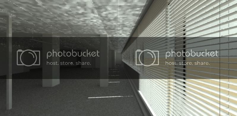
Here is an image of the blinds in an open position.
The resulting image has many reflection spots on the ceiling, which is the problem. The ceiling is mostly just a white material. The floor is a carpet.
Sunny, Sep at noon in New York, windows face south.
···
From: Nick Hubof [mailto:[email protected]]
Sent: Thursday, April 22, 2010 12:19 PM
To: 'Radiance general discussion'
Subject: RE: [Radiance-general] two sided surface
All,
Thanks for the help once again. After some more thought I think the perforate.cal would be great to look at, but considering rendering time (if it will even render, with as many blinds that we have to model) the better route might be the BRTD func. I appreciate all of your help and will let you know how it works out.
Nick
From: [email protected] [mailto:[email protected]]
Sent: Thursday, April 22, 2010 10:31 AM
To: Nick Hubof; 'Radiance general discussion'
Subject: Re: [Radiance-general] two sided surface
Hi Nick,
So if I understand correctly, you have blind geometry modeled at different rotations where you then turn on only the rotation that you want to render. If your blinds only run in one direction then you should be able to apply a rotation to the perforated material. If not then Thomas' suggestion of modifying perforate.cal to use UV coordinates is probably the way to go.
From an accuracy point of view I am not sure that using perforate.cal to model the holes and spacing is actually going to be accurate from the standpoint of evaluating illuminance as the holes are rather small and will be dependent on image resolution. Thus my suggestion to consider trans or BRTDfunc where measured transmittance can be applied. Perhaps others can jump in and let me know if I am missing something on this.
From the standpoint of a luminance simulation, ie a rendering, then if in your views you might actually be close enough to see the holes then using perforate.cal might be nice. But you might want to examine some photos or check out an installation to understand how much of the perforation you actually perceive.
-Jack
Sent from my Verizon Wireless Phone
----- Reply message -----
From: "Nick Hubof" <[email protected]>
Date: Wed, Apr 21, 2010 7:29 PM
Subject: [Radiance-general] two sided surface
To: "'Radiance general discussion'" <[email protected]>
Jack,
Thank you for the suggestions. The series of blind rotations are modeled separately (so that I can easily add and subtract them for the scene) and I have also modeled a little less than half of the blind to be ready for the perforation material.
We would like to match the blinds physically without using a trans material. The project we are working on requires us to match a photo of a space that uses these blinds. We not only want to match the space aesthetically but also have accurate illumination plots and luminance rendering data.
The perorate.cal looks good when the blinds are in the horizontal (open) position, it is when we render the other angles that the perforations become stretched. I have had success in the past altering the axis that these .cal files use, but when I have the blinds angled between straight up/down and horizontal then I run into the problem.
Nick
From: [email protected] [mailto:[email protected]]
Sent: Wednesday, April 21, 2010 5:33 PM
To: Nick Hubof; 'Radiance general discussion'
Subject: Re: [Radiance-general] two sided surface
Hi Nick,
If you are interested in material performance of these blinds, I am not really sure that perforate.cal is what you want use. How are you transforming the geometry of the blinds to get the rotation?
Another way to do this would be to split your blind geometry in half with an opaque half that use the blind mixfunc and a translucent half built either use some combination of trans and mixfunc definitions or perhaps using a simple form of BRTDfunc to account for front and backside reflectance and material transmittance. If I recall correctly the manufacturer provides some transmittance information...
-Jack
Sent from my Verizon Wireless Phone
----- Reply message -----
From: "Nick Hubof" <[email protected]>
Date: Wed, Apr 21, 2010 5:00 PM
Subject: [Radiance-general] two sided surface
To: "'Radiance general discussion'" <[email protected]>
Thank you for the replys. I ended up trying the mixfunc route and that worked well.
So since you fixed that issue, I have one more issue that I don’t know can be resolved easily.
These blinds also have 1/32” perforated holes spaced about 1/32” apart.
Picture: http://i23.photobucket.com/albums/b354/mrhubof/General/DSC_0103.jpg
I have tried the perforate.cal mixfunc, to create this effect, but as I rotate the blinds to simulated them shut or half shut the function doesn’t work, because the blind rotates along the z axis. So what results are elongated holes when the blinds are closed.
void mixfunc Perforation_Chrome
6 Chrome void z_hole perforate.cal -s 0.00079375
0
1 0.4
If any of you have suggestions to get around this issue it would be much appreciated.
Thank you again for the help on the previous issue!
Nick
From: [email protected] [mailto:[email protected]] On Behalf Of [email protected]
Sent: Wednesday, April 21, 2010 3:35 PM
To: Radiance general discussion
Subject: Fwd: Re: [Radiance-general] two sided surface
Hi All,
I meant for this to go to the group...
-Jack
Sent from my Verizon Wireless Phone
----- Forwarded message -----
From: "[email protected]" <[email protected]>
Date: Wed, Apr 21, 2010 4:13 PM
Subject: Re: [Radiance-general] two sided surface
To: "Nick Hubof" <[email protected]>
Hi,
The following assumes geometry with uniform normal orientation.
void plastic concave
0
0
5 .5 .5 .5 0 0
void metal convex
0
0
5 .8 .8 .8 .8 0
void mixfunc blind
4 concave convex if(Rdot,1,0) .
0
0
Then apply the blind material to your geometry. You will need to correctly define the convex and concave materials for your needs. You will also need to check that's the materials are showing up on the correct sides. One way to do this is to first define the convex and concave materials as red and blue for an easy visual check. If you need to reverse the materials then simply swap the names in the blind material definition.
Hope this helps.
-Jack de Valpine
Sent from my Verizon Wireless Phone
----- Reply message -----
From: "Nick Hubof" <[email protected]>
Date: Wed, Apr 21, 2010 12:23 PM
Subject: [Radiance-general] two sided surface
To: <[email protected]>
I am modeling a large amount of physical blinds in an office scene. I am
replicating a Warema blind that has an opaque surface (grey) on the convex
side and a chrome surface (93% reflective) on the concave side. To minimize
the amount of geometry I was hoping there is an easy way to apply two
materials to the curved plane instead of adding a thickness and more than
double the geometry.
I have searched the knowledge database and could not find what I was looking
for. I hope there is an easy way to do this.
For instance the surface normal is the chrome material and the opposite side
is the opaque material.
Thank you in advance.
Nick