I have been looking into ways to implement the view angle and direction to irradiance calculation (preferably with the ‘rtrace’ program but I am sure if that’s possible) as an input to calculate the radiant flux for a given field of view, to compute the average radiance across a particular field of view (watts reaching a defined field of view). My priority is to use solid angles as input to the program.
If anyone has experience in this area, I’d appreciate any tips you may have.
Thanks!
I’m not 100% sure what you are asking, but you might want to look at the rsensor tool, which takes an angular sensitivity function and traces importance samples to estimate a specific sensor output.
Cheers,
-Greg
P.S. I don’t know where to find the man page on the website, so I’m including it below for convenience.
Thanks a lot for your reply. I think this is the program I can use and I have been experimenting with it. However, I would appreciate it if you can please clarify the angular sensitivity to me since I am using the program for research purposes. Is this the sensor sensitivity and how do I define it?
I assume a program such as ‘trance’ functions in a similar way but based on coordinates and vectors, if so how is the sensitivity defined for it?
I’m not familiar with the “trance” program, so I don’t know what to say about that.
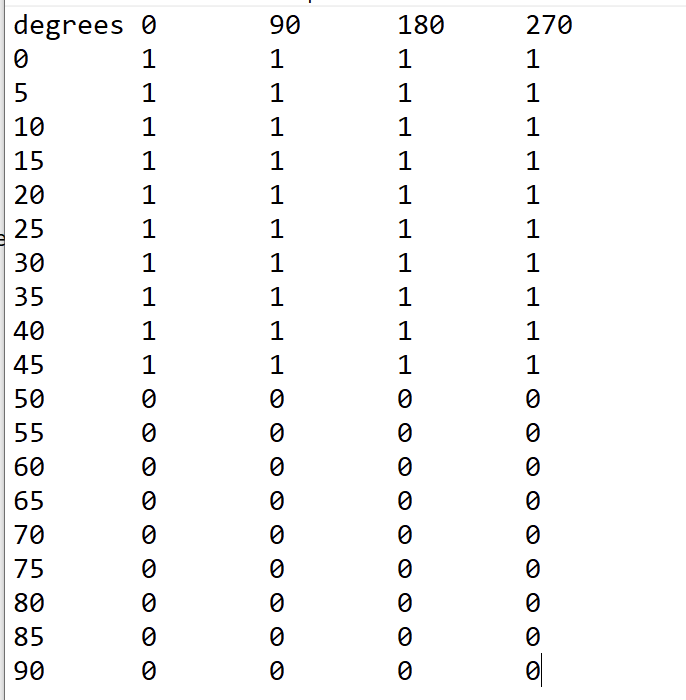
Regarding the Radiance “rsensor” tool, the man page shows how the sensor sensitivity is given as a spreadsheet, where relative sensitivity is organized into columns representing different azimuthal angles and rows of different polar angles. A polar angle of theta=0 corresponds to the view direction specified in the command-line view arguments (-vd) for that sensor. The -vu (view up) vector specifies the direction corresponding to a zero (phi=0) azimuthal angle, with positive angles following the right-hand rule (i.e., clockwise when looking in the -vd direction).
The sensitivity values will act as multipliers against the integrated radiances, essentially acting as an interpolated function over the (partial) sphere where samples are sent.
Thank you for the information and I appreciate your help.
About “trance”, I meant ‘rtrace’. I am sorry, I think my keyboard automatically changed the word.
So, does ‘rtrace’ use a built-in sensitivity function with the maximum sensitivity in the defined vector direction? If so, how are the sensitivity values defined for it?
Ah - gotta love autocorrect! The rtrace values are in watts/sr/meter^2 (i.e., radiance) if your scene is defined properly, or in watts/meter^2 (i.e., irradiance) with the rtrace -I or -i options. The rsensor program multiplies these values by whatever sensitivity coefficients you specify. If you were to define a hemisphere of coefficients, where each coefficient was the cosine of theta at that position, then rsensor would return irradiance (by performing the correct cosine-weighted integral).
In reality, rsensor does something slightly different and more efficient, which is it chooses samples based on the given weighting, sending more primary rays in the direction of greater sensitivity. That way, you don’t waste any samples on regions you don’t care about, and the final result is more accurate for a given number of ray samples.
And this gives me 4 lines of RGB values on Command Prompt. I was wondering how I can create the output in a separate file (similar to the output file for rtrace).
what is the default if I am not using the -vu option?
The sensitivities are not interpolated – rsensor takes the closest value. If you give only 4 phi angles, the closest will be 270 if phi is between 225 and 315°, and 0 if phi is between 315 and 45°.
rsensor can take multiple views in one command, and produces the output values in order. So, you can use:
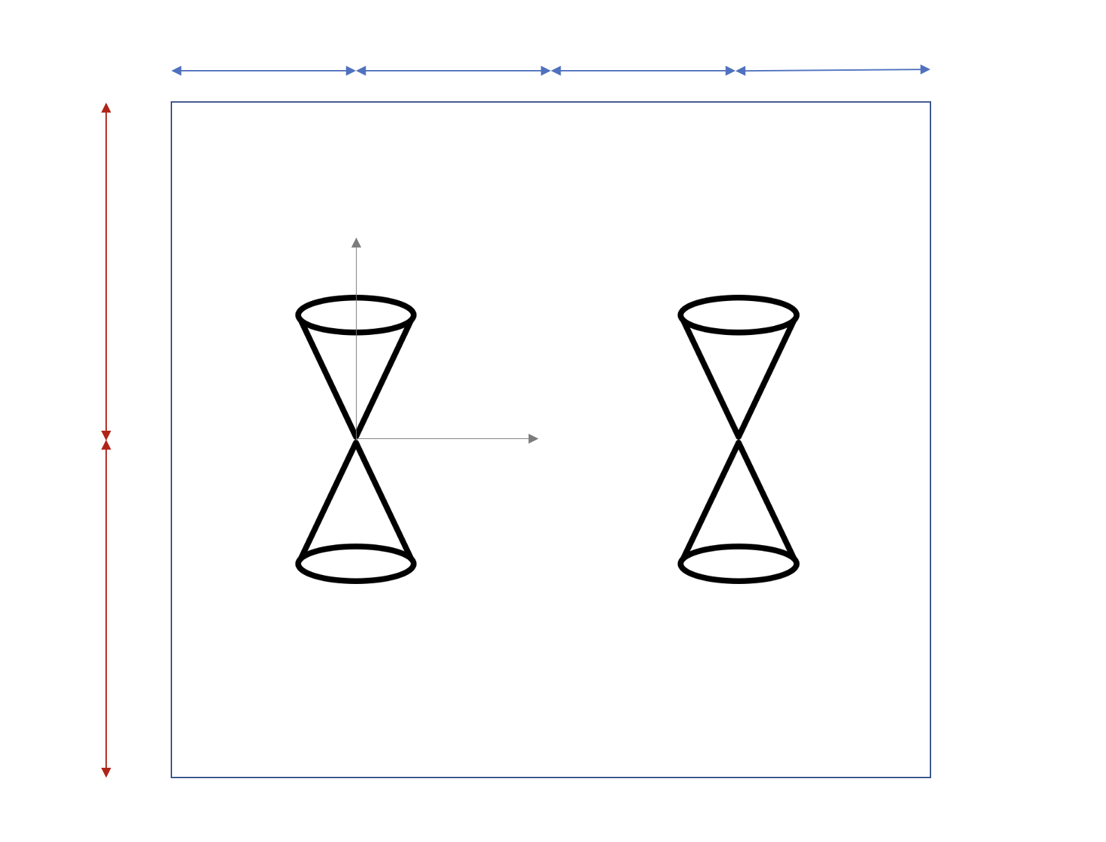
I came across another issue with my calculations. For testing the rsensor program, I had my setup for a square room with either one luminaire (symmetrical distribution) in the center of the ceiling in one scenario and with 4 luminaires of the same type all placed at the same distance from all walls.
I used rsensor to calculate radiant flux for 90 degrees field of view at 2 different viewpoints, with 2 opposite view directions at each point (I tried to visualize this in the figure below, even though it is not an accurate representation I hope it helps to better communicate my problem here. The blue and red arrows each represent the same distances to one another)
And my expectation is that I’d get identical or. similar values for each rsensor calculation since the room is a square, all walls have the same reflectance levels, the viewpoints are located at the same distance to the walls, and luminaire(s) are arranged uniformly in the ceiling or located in the center. But I get 4 different values, and I can’t see why.
I’m not sure what’s going on, either. You should get the same values. Can you upload your file, somewhere, so I can look at it? Or, you could generate 4 views corresponding to your 4 sensors to see what you can see.
Sorry for not replying earlier. I wanted to run more simulations, but I realized it was the IES file (I did the calculations for luminous flux in different angles, and they don’t match although it was supposed to be symmetrical.)
These are the results for a 5mX5m room and the results for matching sensors (for example A&G - B&H…) are very close (but not identical, because of the random number generator?!).
Sorry, I should’ve guessed it was about the IES file.
Glad you found the source of the larger errors. Your 10% variation is likely due to Monte Carlo sampling. If you give all your different views in a single rsensor call as I suggested in my earlier reply, your calculations will be quicker and more consistent, as they’ll be able to share the same irradiance cache. You can also try increasing the -ad parameter above the value reported by “rsensor -defaults”. Try doubling it, for example.
I have a couple of questions, and I would appreciate your help. I would like to confirm something for my calculations. If I am using rsensor on its own only with the -h option for different angles, that would give me the RGB values for integrated radiances, right?
In this sense, it means integrated across the specified angles by the sensor file? And this integrated radiance would be the same as radiant flux (W) entering that particular solid angle (field of view)?
Also, is there a way that I can account for glare corresponding to each point and direction within each rsensor file?
but I couldn’t find a way to implement the rsensor file into it. I just used the defaults on the findglare page on the website and I don’t know how I should set the “-ga 10-60:10 -av .1 .1 .1” part.
Also, I am not really sure how to interpret the output file:
Findglare only computes glare along a horizontal pan based on a specified view and a set of left/right angles. The sensor file, which applies weights to a given set of sample directions in rsensor, is not accepted by findglare or any other Radiance tool.
The output of findglare can be read by glarendx to compute any of the following metrics:
Usage: glarendx -t type [-h] [input]
where ‘type’ is one of the following:
dgi Daylight Glare Index
brs_gi BRS Glare Index
ugr Unified Glare Rating
guth_vcp Guth Visual Comfort Probability
cie_cgi CIE Glare Index (Einhorn)
guth_dgr Guth Disability Glare Rating
vert_dir Direct Vertical Illuminance
vert_ill Total Vertical Illuminance
vert_ind Indirect Vertical Illuminance
You can also use the evalglare program to perform this calculation, and it will likely do a better job at it.
Could you also let me know what you think about the questions below, please?
If I am using rsensor on its own only with the -h option for different angles, that would give me the RGB values for integrated radiances, right?
In this sense, it means integrated across the specified angles by the sensor file? And this integrated radiance would be the same as radiant flux (W) entering that particular solid angle (field of view)?
The -h option just leaves off the header information, so that isn’t particulary relevant to your question as I understand it.
Typically, the output of rsensor is used as a relative rather than an absolute value, as when modeling the signal out of some kind of masked light sensor (hence the name).
I don’t know what your rsensor input file looks like. If it has a set of angles where the sensitivity is all 1’s, then I believe it will give you the radiance integral of the included solid angle in watts/meter^2. In other words, the computed radiance (which is in watts/sr/meter^2) over the region gets multiplied by the solid angle you are sampling in steradians, which results in units of watts/meter^2.
In the special case where you are integrating over a hemisphere and the sensitivities are computed as the cosine of the angle to the surface normal, then rsensor should compute a standard irradiance metric in watts/meter^2.
I don’t know what your rsensor input file looks like. If it has a set of angles where the sensitivity is all 1’s, then I believe it will give you the radiance integral of the included solid angle in watts/meter^2. In other words, the computed radiance (which is in watts/sr/meter^2) over the region gets multiplied by the solid angle you are sampling in steradians, which results in units of watts/meter^2.
Regarding this region that the computed radiance is integrated over its solid angle, so is this region a projected area? Or part of the surface of a sphere?
I am trying to understand what the area would be to calculate the radiant flux.
To get from units of watts/meter^2 to radiant flux (in watts) you need to integrate over some surface area. The rsensor calculation is giving you the differential quantity from a point, so while it is related to radiant flux/power, it needs another integral to get to actual energy/unit_time (power). So, just pick an area you want to integrate over, such as a surface or object the flux is landing on or a pane of glass the flux is passing through.
Technically, you should compute the integrals together as part of a combined sampling method, but if the surface is flat and the surrounding geometry is far enough away, it shouldn’t matter. Multiplying the rsensor result at the center of the object and multiplying by the surface area is acceptable.
Just to make things simple for myself, I considered a flat surface and calculated the area that I needed to multiply the irradiance (watts/m^2) by the area. So this would be just an approximation, and I am not really sure how I can determine if the surrounding geometry is far enough in my calculation case. I based my calculations on a distance of 1.25 meters.
But for exact values, is there a way that I can integrate the watts/m^2 values over a surface area using Radiance itself?