Texture Mapping and colorpict usage

I am at a loss to resolve why my texture mapping always come up square even
though the 'pic' file may have a aspect ratio other than 1 as in the example
below.

I am using Radiance Version 3.8

I use the following procedure (Sketchup Pro V6 to 3ds units millimetres):
# 1. Convert the 'jpg' image to uncompressed 'tif'
# convert -compress none texture.jpg texture.tif
# 2. Create a 'pic' image from the 'tif':
# ra_tiff -r texture.tif texture.pic
# 3. Determine the average red green blue values of the 'pic' image
# ximage texture.pic &
# Left click and drag a rectangle over a representative area of the
image
# Press the letter 'c' to display the values e.g. 0.02,0.45,0.36
# 4. Calculate the appropriate grey values e.g.
# icalc /usr/local/lib/ray/lib/rayinit.cal
# grey(0.02,0.45,0.36)
# $1=0.330185114 printed by the icalc program
# ^C Control C to quit the program
# 5. Copy/create the texture material as a plastic or trans material
# Don't label the material with the final modifier name at this stage
# The red green blue values should be the value of $1 calculated in
the last step
# 6. Create the colorpict entry to link the image and transformation size.
# Size is always taken as the smallest dimension of the image is 1
unit.
# 7. Alias the colorpict and the material to the required modifier name

# size 1219 x 2438 This is the size reported with Sketchup for the use of
this image
void plastic Concrete_Form_4x8
0
0
5 0.423402293 0.423402293 0.423402293 0.000000 0.000000

void colorpict image_data_Concrete_Form_4x8
9 red green blue textures/Concrete.pic . frac(U) frac(V) -s 1219
0
0

image_data_Concrete_Form_4x8 alias Concrete Concrete_Form_4x8

ximage Concrete.pic shows the expected 1 to 2 aspect ratio.

getinfo -d Concrete.pic reports -Y 336 +X 168

I have tried varying the last line of colorpict stanza to add in an aspect
ratio e.g 1 0.5 or 1 2, neither made any difference.

Any thoughts would be appreciated.

Regards

Terry Mc Minn
Faculty of Built Environment, Art and Design
Curtin University of Technology
GPO Box U 1987 Perth 6845
Western Australia
Email: [email protected]
CRICOS Provider Code: 00301J

No virus found in this outgoing message.
Checked by AVG Free Edition.
Version: 7.5.472 / Virus Database: 269.8.5/826 - Release Date: 31/05/2007
4:51 PM
Hi Terry,

In brief you need to add a multiplier for the aspect ratio (<ar>) of the image to one or the other of frac(U) or frac(V).

    void colorpict image_data_Concrete_Form_4x8
    9 red green blue textures/Concrete.pic . frac(U) frac(V)*<ar> -s 1219
    0

For further explanation you can refer to the following two posts, one from Giulio Antonutto and the other from me. Both of these deal with Lu/Lv coordinate mapping as opposed to UV coordinate mapping. But I think that they should still work.

-Jack

RE: [Radiance-general] OBJ2MESH - UV Scale and Shift

hope this helps:

es.

shift by 50% and tile 10 times:

(X(Lu+0.5)/(1/10))-floor(X(Lu+0.5)/(1/10))

or
X(Lu+0.5)/.1-floor(X(Lu+0.5)/.1)

where X is the ratio X/Y of the image to map.

you may use directly these expression in colormap:

void colormap test
7 red green blue picture.pic . (X(Lu+0.5)/.1-floor(X(Lu+0.5)/.1)) ((Lv+0.5)/.1-floor((Lv+0.5)/.1))
0

the "." means no cal file

ciao

giulio

PS remember that you need to recreate the mesh for this to take
effect...
From: [email protected]
[mailto:[email protected]] On Behalf Of
Marcus Jacobs
Sent: 11 August 2005 15:16
To: [email protected]
Subject: [Radiance-general] OBJ2MESH - UV Scale and Shift

Dear Group,

I have been recently using OBJ2MESH as part of my workflow. I am finding
it very useful. What I would like to know is if it is possible to adjust
the UV shift and scale of a pattern associated with a mesh? Say if a pattern
tiles 4 times in the U and V, if I want for it to tile 1,2,3,6,8,etc. times
and I wish to shift the patern by 1/2, is there a method for doing this?

Regards,

Marcus

RE: [Radiance-general] Ambient exclude transformed material in instances

Hi Iebele,

To use local u,v coordinate mapping (Lu,Lv) you need to use obj2mesh rather than obj2rad.

Here is the process for making a mesh element:

    Define mats.tree.rad using simple materials first as an example.
    The names of the materials must correspond to the names of the
    materials indicated for the .obj geometry (take a look in the .mtl
    file to get the names).

        mats.tree.rad:

            void plastic Bark
            0
            5 1 1 1 0 0

            void plastic Leaf
            0
            5 1 1 1 0 0

    Generate tree.rtm as follows:

        obj2mesh -a mats.tree.rad tree.obj > tree.rtm

    Creat tree.mesh.rad as follows:

        tree.mesh.rad:

            void mesh tree
            1 tree.rtm
            0

    Test you mesh:

        objview tree.mesh.rad

Now lets apply more complex materials using local u,v coordinate mapping. To do this you need the following image data:

       1. bark.pic
       2. aspect ratio for bark.pic (y/x), lets call it <arB>
       3. leaf.pic
       4. aspect ration for leaf.pic (y/x), lets call it <arL>
       5. leaf.matte.pic - this is the alpha/matte channel for the
          leaf. The correct way to setup the matte is for white to
          represent the leaf and black to represent what is not the
          leaf. This means that you may have to invert the matte the
          comes from xfrog.

    Now lets create the complex materials in mats.tree.rad

        mats.tree.rad:

            #BARK definition
            void colorpict bark.tile
            7 red green blue Bark.pic . frac(Lu) frac(Lv)*<arB>
            0

            bark.tile plastic Bark
            0
            5 1 1 1 0 0

            #LEAF definition
            void colorpict leaf.tile
            7 red green blue Bark.pic . frac(Lu) frac(Lv)*<arL>
            0

            leaf.tile plastic leaf.map
            0
            5 1 1 1 0 0

            leaf mixpict Leaf
            7 leaf.map void green leaf.matte.pic . frac(Lu) frac(Lv)*<arL>
            0

    Now recompile your mesh:

        obj2mesh -a mats.tree.rad tree.obj > tree.rtm

    Now view it:

        objview tree.mesh.rad

You should add Bark and Leaf to your ambient exclude file/list if you do not want them in the ambient calculation. You can use tree.mesh.rad along with replmarks, xform or some other method to deploy the tree object in the scene.

This should work fine. Let me know if you have any questions.

-Jack

Gregory J. Ward wrote:

Hi Iebele,

I can't be much help on this, as I'm not familiar with the model, but the general idea with local coordinates is that you don't have to do the mapping yourself. It's supposedly handled by the mesh generation software, and isn't affected by transformations as a global coordinate mapping would be.

I hope this is a helpful clue, as it's about all I have to offer.
-Greg

From: iebele <[email protected]>
Date: April 3, 2007 8:39:12 AM PDT

Thanks Greg an Jack for your excellent and very helpfull suggestions.

I now have succesfully converted the .obj file to rad, using obj2rad ( polytrans did indeed work with Xfrog obj-files, but meshlab did not accept these files Lars ).

However I can't get the mapping right. I've tried a lot, but with no succes. Would you please share with me an example of the materials you use for the bark and the leaves?

I just don't really understand when and how to use Lu and Lv or frac(Lu) and frac(Lv) in the colorpict modifier and how these can ever be placed in a reasonable way on each triangle in the output of obj2rad, which in my case is like :

leaf_col_leaf2 polygon leaf22836.60976
0
9
        -0.250204 0.195593 13.838
         -1.00383 -0.956752 13.8816
         -1.21881 -0.19178 13.5622

I never really understood the meaning of texture-coordinates, but at this time I feel that is what is missing here.

Is there a difference in using obj2rad and obj2mesh for this purpose ? I tried both but with the some odd results concerning the coordinate mapping.

-Iebele

Terrance Mc Minn wrote:

···

-----Original Message-----

I am at a loss to resolve why my texture mapping always come up square even though the 'pic' file may have a aspect ratio other than 1 as in the example below.

I am using Radiance Version 3.8

I use the following procedure (Sketchup Pro V6 to 3ds units millimetres):
# 1. Convert the 'jpg' image to uncompressed 'tif'
# convert -compress none texture.jpg texture.tif
# 2. Create a 'pic' image from the 'tif':
# ra_tiff -r texture.tif texture.pic
# 3. Determine the average red green blue values of the 'pic' image
# ximage texture.pic &
# Left click and drag a rectangle over a representative area of the image
# Press the letter 'c' to display the values e.g. 0.02,0.45,0.36
# 4. Calculate the appropriate grey values e.g.
# icalc /usr/local/lib/ray/lib/rayinit.cal
# grey(0.02,0.45,0.36)
# $1=0.330185114 printed by the icalc program
# ^C Control C to quit the program
# 5. Copy/create the texture material as a plastic or trans material
# Don't label the material with the final modifier name at this stage
# The red green blue values should be the value of $1 calculated in the last step
# 6. Create the colorpict entry to link the image and transformation size.
# Size is always taken as the smallest dimension of the image is 1 unit.
# 7. Alias the colorpict and the material to the required modifier name

# size 1219 x 2438 This is the size reported with Sketchup for the use of this image
void plastic Concrete_Form_4x8
0
5 0.423402293 0.423402293 0.423402293 0.000000 0.000000

void colorpict image_data_Concrete_Form_4x8
9 red green blue textures/Concrete.pic . frac(U) frac(V) -s 1219
0

image_data_Concrete_Form_4x8 alias Concrete Concrete_Form_4x8

ximage Concrete.pic shows the expected 1 to 2 aspect ratio.

getinfo -d Concrete.pic reports -Y 336 +X 168

I have tried varying the last line of colorpict stanza to add in an aspect ratio e.g 1 0.5 or 1 2, neither made any difference.

Any thoughts would be appreciated.

Regards

Terry Mc Minn
Faculty of Built Environment, Art and Design
Curtin University of Technology
GPO Box U 1987 Perth 6845
Western Australia
Email: [email protected]
CRICOS Provider Code: 00301J

No virus found in this outgoing message.
Checked by AVG Free Edition.
Version: 7.5.472 / Virus Database: 269.8.5/826 - Release Date: 31/05/2007 4:51 PM
------------------------------------------------------------------------

_______________________________________________
Radiance-general mailing list
[email protected]
http://www.radiance-online.org/mailman/listinfo/radiance-general
  
--
# Jack de Valpine
# president
#
# visarc incorporated
# http://www.visarc.com
#
# channeling technology for superior design and construction

hope here you can find something useful:
http://web.mac.com/geotrupes/iWeb/Main%20site/RadBlog/3690C181-7F9F-43AD-B5B
2-A5D239AD503E.html
and if you use obj2mesh... remember that the mesh need to be regenerated at
any change since it is frozen...
ciao
G.

···

On 1/6/07 16:28, "Terrance Mc Minn" <[email protected]> wrote:

I am at a loss to resolve why my texture mapping always come up square even
though the 'pic' file may have a aspect ratio other than 1 as in the example
below.

I am using Radiance Version 3.8

I use the following procedure (Sketchup Pro V6 to 3ds units millimetres):
# 1. Convert the 'jpg' image to uncompressed 'tif'
# convert -compress none texture.jpg texture.tif
# 2. Create a 'pic' image from the 'tif':
# ra_tiff -r texture.tif texture.pic
# 3. Determine the average red green blue values of the 'pic' image
# ximage texture.pic &
# Left click and drag a rectangle over a representative area of the
image
# Press the letter 'c' to display the values e.g. 0.02,0.45,0.36
# 4. Calculate the appropriate grey values e.g.
# icalc /usr/local/lib/ray/lib/rayinit.cal
# grey(0.02,0.45,0.36)
# $1=0.330185114 printed by the icalc program
# ^C Control C to quit the program
# 5. Copy/create the texture material as a plastic or trans material
# Don't label the material with the final modifier name at this stage
# The red green blue values should be the value of $1 calculated in the
last step
# 6. Create the colorpict entry to link the image and transformation size.
# Size is always taken as the smallest dimension of the image is 1 unit.
# 7. Alias the colorpict and the material to the required modifier name

# size 1219 x 2438 This is the size reported with Sketchup for the use of this
image
void plastic Concrete_Form_4x8
0
0
5 0.423402293 0.423402293 0.423402293 0.000000 0.000000

void colorpict image_data_Concrete_Form_4x8
9 red green blue textures/Concrete.pic . frac(U) frac(V) -s 1219
0
0

image_data_Concrete_Form_4x8 alias Concrete Concrete_Form_4x8

ximage Concrete.pic shows the expected 1 to 2 aspect ratio.

getinfo -d Concrete.pic reports -Y 336 +X 168

I have tried varying the last line of colorpict stanza to add in an aspect
ratio e.g 1 0.5 or 1 2, neither made any difference.

Any thoughts would be appreciated.

Regards

Terry Mc Minn
Faculty of Built Environment, Art and Design
Curtin University of Technology
GPO Box U 1987 Perth 6845
Western Australia
Email: [email protected]
CRICOS Provider Code: 00301J

No virus found in this outgoing message.
Checked by AVG Free Edition.
Version: 7.5.472 / Virus Database: 269.8.5/826 - Release Date: 31/05/2007 4:51
PM
_______________________________________________
Radiance-general mailing list
[email protected]
http://www.radiance-online.org/mailman/listinfo/radiance-general

____________________________________________________________
Electronic mail messages entering and leaving Arup business
systems are scanned for acceptability of content and viruses

Thanks, Guilio -- I hadn't seen this. I especially like the tutorial pages; you and Andrew do really nice work. It's great to have a page to point beginners to -- is this linked on the main site at all?

-Greg

http://web.mac.com/geotrupes/iWeb/Site/Tutorials.html

···

From: giulio antonutto <[email protected]>
Date: June 1, 2007 12:50:08 PM PDT

hope here you can find something useful:
http://web.mac.com/geotrupes/iWeb/Main%20site/RadBlog/3690C181-7F9F-43AD-B5B2-A5D239AD503E.html
and if you use obj2mesh... remember that the mesh need to be regenerated at any change since it is frozen...
ciao
G.

thanks for the feedback :slight_smile:
it is an honour!
It is a choral work from Andrew and me...
We really hope it will help people to start :slight_smile:
G.

···

On 2/6/07 14:24, "Gregory J. Ward" <[email protected]> wrote:

Thanks, Guilio -- I hadn't seen this. I especially like the tutorial
pages; you and Andrew do really nice work. It's great to have a page
to point beginners to -- is this linked on the main site at all?

-Greg

http://web.mac.com/geotrupes/iWeb/Site/Tutorials.html

From: giulio antonutto <[email protected]>
Date: June 1, 2007 12:50:08 PM PDT

hope here you can find something useful:
http://web.mac.com/geotrupes/iWeb/Main%20site/RadBlog/
3690C181-7F9F-43AD-B5B2-A5D239AD503E.html
and if you use obj2mesh... remember that the mesh need to be
regenerated at any change since it is frozen...
ciao
G.

_______________________________________________
Radiance-general mailing list
[email protected]
http://www.radiance-online.org/mailman/listinfo/radiance-general

____________________________________________________________
Electronic mail messages entering and leaving Arup business
systems are scanned for acceptability of content and viruses

Hello everyone,

I’ve recently started working with texture mapping and colorpict usage. My goal is to have a rectangle block, whicht gets assigned a pattern defined by a pic-file. First of all I’ve got the same problem as @Terrance_Mc_Minn , which is that the texture mapping always comes up square even. I already tried the solution from @Jack_de_Valpine but it doesnt work for me. Futhermore my pattern gets repeated over the whole rectangle more then once and I dont know how to change this. I already tried to scale it up with -s but it did not work for me. Any advices would be nice. With this Dropbox Link you can see what I’ve I already did. Dropbox - Radiance - Texture Mapping - Simplify your life

Furthermore the links from @Giulio_Antonutto1 and @Greg_Ward expired. Is there any way to get to this information.

Greetings Philip

Which links are you referring to? The names are not enough for us to know.

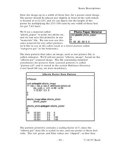
Regarding colorpict coordinates, we definitely need this in a FAQ, which we don’t have. The simplest example may be in an old deprecated tutorial written by Cindy Larson on page 59, excerpted below:

Note the importance of including the correct rotations, translations, and scaling.

Hello,

I refered to the links:

  1. http://web.mac.com/geotrupes/iWeb/Main%20site/RadBlog/3690C181-7F9F-43AD-B5B
  2. http://web.mac.com/geotrupes/iWeb/Site/Tutorials.html

Furthermore I understand the importance of including the correct rotations, translations and scaling but what I dont understand is why the pattern given by the pic-file is always a square and how I can give an aspect ratio to it so it is not square anymore. In my understanding the operations rotation, translation and scaling (scaling scales up the pattern in every dimension, am I right?) should not have an impact on the fact that my pattern is always a square.

I’ve already tried the solution:
void colorpict cell_pattern
7 red green blue solarcell.pic . frac(U) frac(V)*
0

but this seems to not work for me. But I’m not sure either how its meant. I tried diffrent approches:

  1. 7 red green blue solarcell.pic . frac(U) frac(V)* ; then I get the error: < is an unexpected character
  2. 7 red green blue solarcell.pic . frac(U) frac(V)*1.65 ; where 1.65 is my aspect ratio and then than the pattern is still a square .

I would be greatful for any kind of advice how to achieve a rectangular pattern.

Greetings Philip

Hi Philip,

I am not too involved in this these days, however, looking at your post I think the problem may be in the multiplier of 1.65 that you are applying to frac(V). If you look back at my earlier posting on the topic you will note that the the multiplier is y/x applied to the y aspect of the image [frac(V)]. I believe that U,V coordinates are in a 1:1 space. So the largest size of the image map is always 1. I think this means the following:

Horizontal aspect image map = 1 to y/x of image
Vertical aspect image map = x/y of image to 1

which should apply as follows:

Horizontal image map:

void colorpict imap
7 red green blue imap.pic . frac(U) frac(V)*<y/x of image>
0

Vertical image map:

void colorpict imap
7 red green blue imap.pic . frac(U)*<x/y of image> frac(V)
0

This is all plumbing the depths of my memory on this so it is very possible that I am forgetting something, but worth a try nevertheless.

Best,

-Jack

Hi guys,

Thanks for the tipps @Jack_de_Valpine but it still doesnt work. I’ve spend hours trying to make this work but I’m not able to do it. It still doesnt seem that the pattern that I get is a rectangle its always a square. I dont understand it. Ive got a rectangle with a length of 1.64 in the x-direction and a length of 0.992 in the y-direction. The pattern that I want on this rectangle is a blue surface with a silver/white border. I generated this and to check the dimensions of the dimensions I used “getinfo -d” and I got Y=1938 and X = 1172 (so I assumed that I need to rotate the pattern 90° around the z axis. ) . Furthermore I used a scaling factor of 0.992/1.64 = 0.60 for frac(U). With this my intention was to achieve a rectangular pattern but it didnt work. I also tried diffrent translations like -t 1.64/2 0.992/2 0 with the goal to center the pattern. Furthermore I thought that I might need to scale the pattern and I tryied -s 0.992 and -s 1.64 but this doesnt seem to work too. I’ve updated the dropbox files (Dropbox - Radiance - Texture Mapping - Simplify your life). If anyone has a clue to put this simple pattern the right way on a rectangle please reach out to me. Im grateful for any kind of advice .

Geetings Philip

Thanks for uploading your files. I changed:

void colorpict cell_pattern
15 red green blue solarcell.pic . frac(U)*0.6 frac(V) -s 1 -t 0 0 0 -rz 90 
0
0

to:

void colorpict cell_pattern
9 red green blue solarcell.pic . frac(U) mod(V,1938/1172) -s .5
0
0

This seems to have resolved the problem.
-Greg

Hi @Greg_Ward,
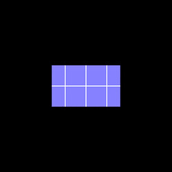
and thanks for your fast reply. If run
rad vis.rif
with the changes you wrote I get the following result:

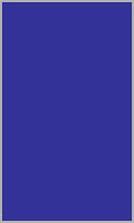
But this is not what I wanted. My goal was to generate one big blue surface with a white/silver border. Like this:

If I did or understand anything wrong please tell me.

Greetings Philip

Ah, OK. That wasn’t clear. I thought you were trying to tile the pattern, since that was what your first attempt seemed to imply. Getting a single tile mapped onto the surface can be done with:

void colorpict cell_pattern
13 red green blue solarcell.pic . Py Px -s 1.984 -t -1.64 -.992 0
0
0

I have swapped the Px and Py coordinates rather than rotating the surface, but you could do it either way. The scaling factor makes the smaller side match the dimensions of the object, which getbbox tells me:

% getbbox solarcell.rad
     xmin      xmax      ymin      ymax      zmin      zmax
    -1.64      1.64    -0.992     0.992      -0.1       0.1

I also translated the origin of the pattern to the smallest x and y values to align everything.

It would be better to have your materials defined in your object file in this case, so any transforms you apply (with xform for example) will apply to the pattern as well.

Hi Greg,

and sorry for the communication error. First of all I’ve wanted to thank you but I have also a few more questions.

  1. What exactly is the difference between the frac(U) frac(V) method and the Px Py method?
  2. To test my understanding I’ve shrinked the object and rotated it 45 deg around the Z and 45 deg around the Y-axis. Then I tried to align the pattern again (in the wanted way → blue surface with white border) and I thought I only needed to change the cell_pattern definition in the following way:
17 red green blue solarcell.pic . Py Px -s 0.992 -t -0.82 -.496 0 -rz 45 -ry 45 

I’ve again updated the files in the dropbox (Dropbox - Radiance - Texture Mapping - Simplify your life) but the result was not something I expected.

Again I would be grateful for further help.

Greetings Philip

Hi, blast from the past. 14 year after!!!
The whole trick is to do the UV mapping elsewhere and then refer to the UV coordinates into the material file and use obj2mesh.
one of the annoying things is the ratio of the image but it is all doable. The PDF should be ok, in case I can send you an example.
G.
details as follows:

There is an easy way to use UV mapping, even for procedural texture…just create an UV mapped .obj model, save, edit the radiance material file and use:

obj2mesh -a materials model.obj > model.mesh

now load the mesh with the primitive mesh in a radiance file and save as model.rad

void mesh id

1 model.mesh

0

0

Note that mesh cannot have light in it!

Light can stay in a mesh BUT they do not work.

Also mesh are FROZEN, any change will require to regenerate the mesh.

To attach a pattern (tif image) you need first to convert it to Radiance HDR:

ra_tiff -r image.tif image.pic

This generally works but may have problem with more exotic tiffs, just use a plain type. Now you need to get the ratio between horizontal and vertical images resolution:

getinfo -d image.pic | rcalc -e '$1=$5/$3’

Note that this number, (W/H), need to be > 1, so if the ratio is 0.8 you need to consider 1/0.8 (i.e. H/W) instead; This image ratio is referred to as R in the following notes.

Let’s define few things:

to scale the image, scale is:

Su,v 1 = 100%, 0.5 = 50% and so on

if you need to translate, in fraction of u,v, the parameter is:

Tu,v 1 = 100%, 0.5 = 50% and so on

the image ratio is defined by two values, one is a unit (1) and the other the previous R value:

Ru,Rv thus 1,R or R,1

The material definition, verbose style:

void colorpict image

7 red green blue image.pic . R*((Lu-Tu)/Su-floor((Lu-Tu)/Su)) 1*((Lv-Tv)/Sv-floor((Lv-Tv)/Sv))

0

0

or

void colorpict image

7 red green blue image.pic . 1*((Lu-Tu)/Su-floor((Lu-Tu)/Su)) R*((Lv-Tv)/Sv-floor((Lv-Tv)/Sv))

0

0

then connect to a base material

image plastic material

0

0

5 1 1 1 0 0

A material definition, with indexes is as follows

void colorpict image

7 red green blue image.pic . A1*((Lu-A3)/A5-floor((Lu-A3)/A5)) A2*((Lv-A4)/A6-floor((Lv-A4)/A6))

0

6 Ru Rv Tu Tv Su Sv

edit the Ry, Rv Tu Tv etc. with the values desired.

6 A1 A2 A3 A4 A5 A6

New possibilities…

Imagine, once you have Lu and Lv defined you can use them instead of Px Py Pz… so all the procedural pattern, like wood, marble , waves… they all become immediately ready for any surface!

1 Like

Also, a side note, you should find some useful tools from 2014 radiance workshop here:
https://www.radiance-online.org/community/workshops/2014-london/presentations/day2/Antonutto_SummerSale.pdf
and here:
https://www.radiance-online.org/community/workshops/2014-london/presentations/day2/Article4.zip

hope it is of help!

1 Like

Hi,

thanks @Giugi for your answer but I have trouble to choose the right Tu,Tv, Su, Sv parameters for my problem.

Furthermore @Greg_Ward do you know what the problem here was:

To test my understanding I’ve shrinked the object and rotated it 45 deg around the Z and 45 deg around the Y-axis. Then I tried to align the pattern again (in the wanted way → blue surface with white border) and I thought I only needed to change the cell_pattern definition in the following way:

17 red green blue solarcell.pic . Py Px -s 0.992 -t -0.82 -.496 0 -rz 45 -ry 45 

I’ve again updated the files in the dropbox (Dropbox - Radiance - Texture Mapping - Simplify your life) but the result was not something I expected.

Greetings Philip

I am going to past into your dropbox a folder with an obj of your model mapped as an example.
the material file reads:


#Paramenters:
#Ru Rv

#the image ratio is defined by two values, one is a unit (1) and the ratio
#Ru,Rv
#getinfo -d image.pic
#-Y 1020 +X 950
#x/y = 1.07368421
#so one is 1 and the other 1.07

#no scaling needed
#Su,v = 1

#no need to translate as it is a UV map
#Tu,v = 0

#definition of the image map works like this

void colorpict image
7 red green blue image.pic . A1*((Lu-A3)/A5-floor((Lu-A3)/A5)) A2*((Lv-A4)/A6-floor((Lv-A4)/A6))
0
6 1 1.07368421 0 0 1 1
#the above is: 6 Ru Rv Tu Tv Su Sv

#u need also a basic plastic material to multiply by
image plastic Material
0
0
5 1 1 1 0 0

#lastly you need to create a mesh like this:
#obj2mesh -a model.mat model.obj > model.mesh

#and load up in a radiance file which will look like:

#void mesh mesh
#1 model.mesh
#0
#0

#I use C4D and that swaps Y and Z so I have to add the transformation rx 90 in

#void mesh mesh
#3 model.mesh -rx 90
#0
#0

ok, your dropbox is not shared, hence here is a link to the same archive I have mentioned:

Hope this is simple to figure out, the key is that once you have used UV you need not to worry about scale, rotation and positions (the PxPyPz you mentioned earlier) as the UV is relative to the mesh.
And if you move, scale, shift the mesh all remain unaltered.
G>

1 Like

I completely agree with Giulio about local coordinates making life easier.

If for some reason you cannot use the mesh type, you can still gain some of the benefits by putting the material description in the same file as your geometry as I suggested. Doing this, any subsequent applications of xform apply the appropriate transform to the material as well, so it all works. This is the recommended method, rather than trying to do everything manually.