Hi Radiance Community,
I’m currently working on a project where I compare data from simple weather measurement devices I built (using a very cheap BH1750 lux sensor) with theoretical values under clear sky conditions, using Radiance. The sensor is shielded by a 3D-printed white PLA dome, which I’ve roughly estimated reduces brightness by about 70%, as measured with an iPhone lux meter. The dome has a radius of approximately 3 cm.
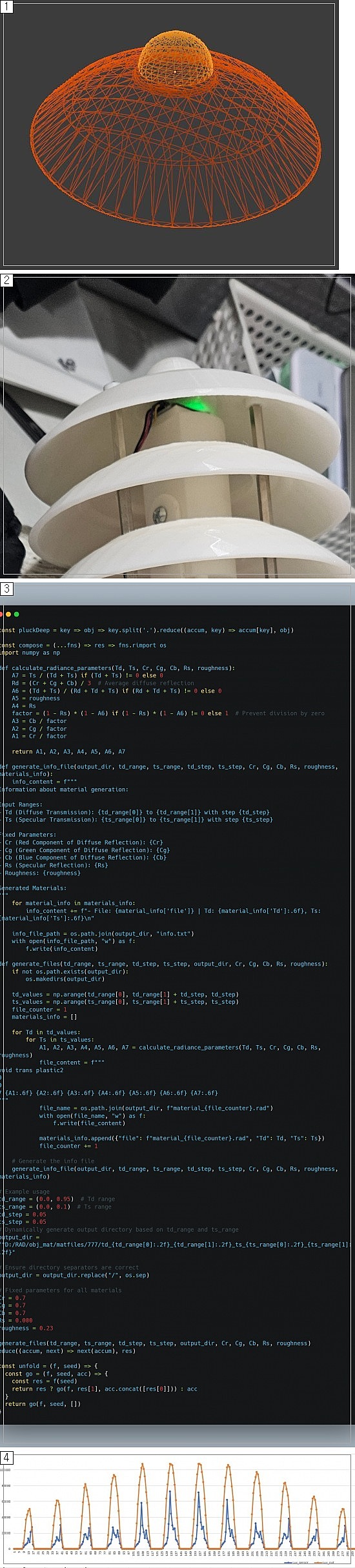
fig1, fig2(newcomers could only include only 1 image so I had put all together in one image)
I’m trying to simulate the shielding effect using Radiance to compare the measured lux values to theoretical results under various clear sky conditions. To model the PLA dome, from reading the RwR textbook I figured `trans’ material would be the likely candidate. As the actual optics of this material was not clear, I made different trans materials with a range of ts and td
fig3
But the results haven’t been satisfactory.
fig4
While the external surfaces around the dome produce realistic parabolic patterns in illuminance, the computed lux values inside the shield (where the sensor is) don’t align with expectations.The results appear abnormal and inconsistent with what I would expect based on the physical measurements.
My advisor suggested exploring BSDF for this purpose. However, most tutorials I’ve found focus on indoor simulations, and I’m unsure how to apply BSDF effectively to this outdoor flat-ground setup. I’m also not sure if BSDF is even appropriate for modeling this kind of shielding effect, as the tutorials seem more focused on window systems or interior lighting.
I’m feeling quite stuck at the moment. How can I accurately model the PLA dome shielding effect for this specific sensor setup? Are there any tips for debugging or improving the sensor area lux calculations to make them align better with physical measurements?
Thanks in advance for your help!