I am studying workflows within Radiance to simulate frit patterns for visual comfort assessments and need help with two Raidance commands. I have been chipping away at getting these answered on various forums and finally found my way to the Radiance Discourses site.
With the help of @mostapha, I have found that colorpict with the picture.cal function allows me to map an image onto a surface (the image acting as a frit pattern). Additionally, there is the mixfunc command with the perforate.cal function, which creates a repeating pattern across a surface - good for uniform dot frit patterns. However, I am looking for a little more clarification on these commands Here are my two remaining questions:
What other commands exist beside -s that can dimension the perforate.cal pattern? Is it possible to set the distance between objects separately from the object size?
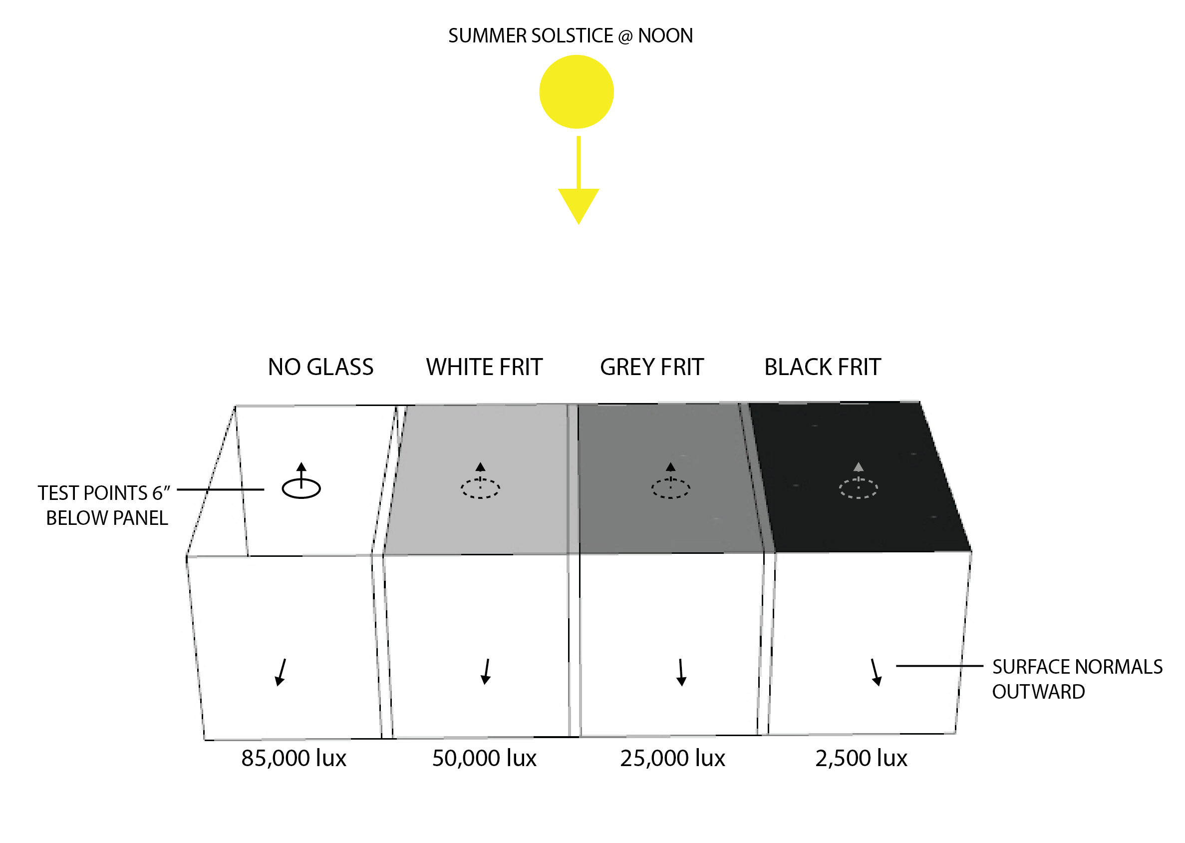
What is the relationship between RGB value in the colorpict and picture.cal commands and the transmissivity? It appears that the RGB value that I set in my image file determines the visible transmittance. I performed a simple box study with windows mapped with solid fills at three different RGB values (black, grey, white) and found a somewhat linear relationship between transmittance and RGB value. The RGB values are black (0,0,0), grey (155,155,155), and white (255,255,255) for the image files used with the colorpict + picture.cal function.
It is difficult to answer your question without seeing your Radiance scene files, especially the way you are using the mixfunc primitive. My guess at your questions is that no, there is no way to move your holes around with a command and yes, the color is affecting your transmission. To move the holes, without affecting their size, you would need to generate new images.
Greg,
Thanks for your reply. Please find the Radiance scene files for the frit RGB test in the dropbox link. Let me know if I am missing any critical scene files. This test was conducted in Rhino using Honeybee.
OK, but you aren’t exactly making this easy. I could not find your mixfunc definition in any of the files on your DropBox page. This is all I am really looking for, not your complete model.
To get the help you seek, please be specific with your questions and provide complete information. You have not said what format your image files are in or how you converted them from 8-bit/channel to Radiance HDR files. This matters to how RGB values translate to transmittance. Radiance files are linear; standard images are not.
sorry for the late reply. The overly long
[discourse.radiance-online.com] marker
makes the actual subject line text disappear in most mail readers, so I
didn’t
notice it earlier. (Can this be removed, please?).
perforate.cal used to be included with Rayfront, but seems to have ended
up
in many places…
This:
https://radiance-online.org:447/pipermail/radiance-general/2002-July/000369.html
seems to be the only other formal publication from my side.
It makes it clear that besides selecting the right output variable,
there is
only one extra parameter, which specifies the diameter of the holes
relative
to their distance in the grid. By default the spacing is 1 unit, so you
need
the -s to scale the pattern to the desired size.
Thank you for your patience. As a first time poster on this forum, it’s difficult to know what files need to be referenced. To clarify, the files in the Dropbox only rely on the colorpict function and not mixfunc with perforate.cal, which may be the reason the mixfunc definition is missing.
The file format for the uniformly applied frit patterns are converted from .tiff to .hdr using the ra_tiff command. This is being performed in Honeybee’s for Grasshopper’s TIF_to_HDR component, if you are familiar with this tool. The materials definitions have been added to the Dropbox folder in the folder “Black frit materials folder” including the original .tif file that I made for this study.
Do you mind elaborating on how the process of converting to Radiance HDR dictates the transmittance value? Do you have any helpful references? Thank you.
The main reference for how things are converted is the C code itself, which I admit is pretty difficult to follow. For most RGB images, including the one in ra_tiff, the conversion looks roughly like P_real = ((P_byte+.5)/256)^gamma where gamma defaults to 2.2. So, transmittance ends up being P_real for each primary times whatever material parameters are involved. You used 0.654 for your glass transmission, which corresponds to a transmittance of 60%, so multiply that by P_real in your case to get effective transmittance for your frits.