Question about validation of electric lighting simulation in Radiance

Dear Radiance users,

I’ve been working on validation of electric lighting simulation in Radiance by comparing results to the measured illuminance. My set up is rather primitive: 1m x 1m x 1m box with a luminaire (diameter = 0.130 mm) installed on the ceiling. All the interior surfaces of the box are painted with RAL9010 paint, which corresponds to 85% reflectance. I have obtained ies file for the luminaire from the manufacturer. I have ran grey non-spectral simulation (considering even distribution of the spectrum) as well as multi-channel spectral simulation. In both cases my measurements exceeded simulation values by 2-3 times. I can bring the simulation results close to the measurements by tweaking the candela multiplier of the luminaire. However, I am not certain this is the right approach. I assume that the measurements should match simulation values without manipulating candela multiplier in a validation study. Since the set up is really simple I am not sure what could be causing such a difference in magnitude. I’ve tried doing the same using honeybee/grasshopper components but the magnitude also did not match the measured illuminance. What crucial step am I missing here?

Thank you in advance!

Best,

Rita

Hi Rita,

Can you give details of your calculation? Computing interreflections will be very important in the case of 85% reflectance surfaces. The default calculation may not be sufficient. Are you using “rad” or the command line? What command are you using to convert the luminaire data?

-Greg

Hi Greg,

thanks for the quick response. These are the parameters than I am using: dp 64 -ds 0.5 -dt 0.5 -dc 0.25 -dr 0 -st 0.85 -lr 4 -lw 0.05 -ab 5 -ad 4096 -as 1024 -ar 512 -aa 0.20 in the command line. I’ve tried reducing -aa of 0.05 but it didn’t improve my results. I am using ies2rad for conversions.

Best,

Rita

Your options need adjusting – where did you get these recommendations? Try:

-dp 64 -ds .1 -dt .05 -dc .25 -dr 2 -st .03 -lw 1e-4 -ab 5 -ad 4096 -as 1024 -ar 32 -aa 0.15

It’s important that the output of ies2rad match the units of your scene. If you scene is in meters, and you are not specifying a -d* option to ies2rad, then you should be OK.

You could do a “sanity check” by comparing the measured luminance looking directly up at your fixture to the same measurement with a ray in rtrace sent upward to the source in your scene. That’s the next thing I would try.

-G

1 Like

Thank you, Greg. New options helped bring the results closer to the measurements (however the multiplier is still involved). Regarding the sanity check: in case there is the same discrepancy between luminance measurements, is it safe to say that it is necessary to apply multiplier? I’ll have to try this soon.

One more question regarding the options. Here is a schematic plan of my box on the left. Point 1 to 5 are measuring horizontal illuminance - everything seems fine there. Points 6 - 17 are measuring vertical illuminance + 0.20 m ground level. All of the central vertical points (Point 7, 10, 13 and 16) are in accordance with the measured illuminance. However, the corner points (marked in red) have lower illuminance than what is measured. Is there an option which can correct this discrepancy ?

P.S: I used GL Optic SPECTIS 1.0 touch spectrometer with cosine corrected measurement head which is necessary “to eliminate measurement errors which may arise when the light source is not directly above the sensor, but at any angle within the hemisphere of measurement.” Additionally, I used another luxmeter to confirm this.

Best,

Rita

PPS: This is point 17 between point 6 and 16. Not 1. Sorry about the graph.

The corner vertical illuminances would be most sensitive to wall reflectance. If your 85% is even slightly off, it will affect these values strongly. I don’t think it is the calculation parameters in this case, rather the scene specification that may be in error.

I would confirm the multiplier difference first with a measurement directly under the source with the lux meter if you don’t have a luminance probe. You can then check against an illuminance calculation right beneath the source in your model.

I think this is a strong possibility about the reflectance values. I have relied on the claim of the paint manufacturer about this as I don’t have a spectrophotometer to confirm this value. Since this company sells mixed samples of the leftover paint of different bigger manufactures, it’s very likely that this value is not precisely 85%. I will try to run a couple of more simulations with higher reflectance values to see what happens with the corner points.

Great tip about lux meter! Luckily, I’ve done such measurement already, which means that the use of multiplier is justified here.

Thank you for all your inputs, this is all good news to me!

Best,

Rita

Rita, I regularly use .ies photometry files. Ideally your file is from an independent test lab and the angular sampling is reasonably small. If not, the resulting interpolation and photometric distribution will not be as granular as the physically emitted luminaire light. Also, the tested luminaire may have manufacturing differences from the luminaire in your test box. Ideally you have access to a goiniophotometer to create your own photometric file so that you are using the .ies file specific to your sample.

1 Like

Hi Rob,

these are all valid comments. Unfortunately, I don’t have the necessary equipment to create photometric files myself and have to rely on what is provided by the manufacturer. I am wondering what degree of angular sampling should be considered acceptable for validation purposes? The ies file that I am using has 181 vertical angles and 2 horizontal planes.

Best,

Rita

Oh, that’s interesting. With only two horizontal planes, interpolation could be another source of error in the room corners. That didn’t occur to me.

That is, assuming I know what a “horizontal” plane is. Does it mean just measurements at azimuths of 0/180° and 90/270°?

Rita, you mean there are only two horizontal angles? Is this type B photometry? Could you send me the file, or a link to the manufacturer’s web site? (By private message, if necessary.)

Sorry, I must correct myself: c-planes not horizontal planes. The luminaire has a circular 2D shape. I don’t know a lot about how interpolation takes place but wouldn’t the number of c-planes be a bigger problem in a, say, rectangular shaped luminaire? A more basic question would be: is there a golden standard about the number or gamma angles and c-planes ies file should have to be considered reliable?

Best,

Rita

Randolph, it is type C photometry. Here is the link to the manufacturer’s website: MEGATRON - Professionelle LED-Leuchten von der IDV GmbH. Sorry that it is in German. If you scroll down you can see IES icon, by clicking “Lichtkurve” below the icon you can download the ies files.

Unfortunately I cannot share the files here due to unauthorized extension.

Best,

Rita

Thanks.

The luminaire is a 165mm diameter surface-mounted LED disk, pointing downward. The IES file describes the geometry as a point.

The header comments say that an EVERFINE GO-2000 goniophotometer was used. Despite the information in the file, it is in fact a type A goniophotometer, so I suppose a coordinate transformation was used to produce the file.

Examining the file, I see that there are only two horizontal angles given which, if I am reading the standard correctly, means that measurements are taken in two vertical planes, one in “front” of the luminaire and one 90° to the left. [Except that this is a type A goniophotometer, which means what I previously wrote is entirely wrong. Corrections next week.]

One thought: since the shape is nominally a point, Radiance will represent that as a 1mm sphere. Is it sufficiently below the “ceiling” of the simulated box? The luminaire is 15mm thick – that might be a good distance below the ceiling for the sphere.

Thank you for taking a look!

This is correct, the luminaire has a 165mm diameter. I previously mentioned 130mm since this is the diameter of the luminous opening. Perhaps a silly question: what does “describes geometry as a point” mean? Should geometry of the luminaire be somehow integrated in the model?

The luminaire is placed below the ceiling, I don’t think there is an error here. Additionally, I tried increasing reflectance of the surfaces to see if it can explain discrepancies in the corners but it affected all points significantly, not just the ones in the corner.

Best,

Rita

@Greg_Ward Given the high reflectance covering almost the entirety of the environment, might the ‘integrating sphere effect’ be a factor? If you recall, the 2005 Solar Energy paper on ‘Reliable datasets for lighting programs validation – benchmark results’ [1] determined that:

“…Lightscape has the best accuracy for this test, while Radiance presents considerable underestimation of indirect illuminance for reflectance values of 0.8 and above.” (See figure below).

Turned out (of course) that there was a perfectly good reason for this behaviour: the AVGREFL = 0.5 (set at compilation). In short, with this setting, Radiance assumes that the environment has an (area weighted) average reflectance of 0.5 – which works for the overwhelming majority of realistic spaces. But not for (practically implausible) spaces where the average reflectance is very high.

[1] F. Maamari, M. Fontoynont, A. Tsangrassoulis, C. Marty, E. Kopylov, and G. Sytnik. Reliable datasets for lighting programs validation–benchmark results. Solar Energy, 79(2):213–215, 2005.

The assumption of 0.5 for reflectance affects the number of rays sent, but it is the -ab value that limits the tail energy. Obviously, it works best to have a good estimate of the final average radiation in the space, so setting -av 0 0 0 (the default) will always under-estimate to some degree.

The studies @John_Mardaljevic points out were done some time ago, and although the 0.5 average reflectance assumption has not changed, other aspects of the calculation have, so that there isn’t the same cap on ray depth that this assumption once implied.

There are three workarounds if this is the issue. The least expensive is to set a sensible -av value approximating the average radiance of all surfaces, or around -av 2.8 2.8 2.8 in your current scene. The second would be to increase the -ab setting to 7 or even 9. The third would be to set -aa 0, which will turn off irradiance caching, with it’s built in average reflectance assumption. If you use this option, I recommend also using Russian roulette sampling, which means setting -lr -10 or so. (The negative turns on RR.)

1 Like

I don’t think the size of the luminous opening accounts for your results but, just in case, here’s an explanation. The IES file format encodes shapes of luminous opening in its width, length, and height values, but in the files I downloaded these are all zero, so it describes a point. If you want the files to describe a 130mm disk, set the length and width to -0.130 and leave the height at zero.

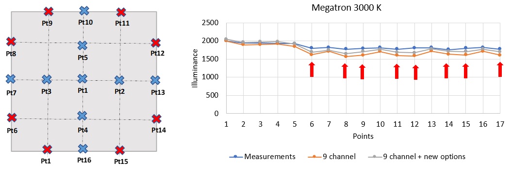
The file provides accurate data in only two planes – one parallel to the x axis and one perpendicular. These are the planes where you are (with a multiplier) getting accurate results. It is possible that, had data been gathered from more horizontal angles, your results would be better.

Anyhow, here’s a formatted version of the IES file, so you can look for yourself.

Version: 2002
Label:
['[TEST] PR165M-PL043CMW-12W80-230 NW',
 '[TESTLAB]',
 '[TESTDATE] 09 May 2019',
 '[ISSUEDATE] 2019-05-09 18:33:38',
 '[NEARFIELD]',
 '[LAMPPOSITION] 0,0',
 '[OTHER] EVERFINE GO-2000A_V1 SYSTEM',
 '[MANUFAC]',
 '[LUMINAIRE] PR165M-PL043CMW-12W80-230 NW',
 '[OTHER]',
 '[OTHER] Gamma(deg)    Fz(lm)      Ft(lm)     %Lum    %Lamp',
 '[OTHER]   0- 10        34.50       34.50     3.38     3.38',
 '[OTHER]  10- 20        98.86      133.36    13.05    13.05',
 '[OTHER]  20- 30       149.77      283.13    27.71    27.71',
 '[OTHER]  30- 40       180.21      463.34    45.34    45.34',
 '[OTHER]  40- 50       185.62      648.97    63.51    63.51',
 '[OTHER]  50- 60       165.18      814.14    79.67    79.67',
 '[OTHER]  60- 70       123.21      937.36    91.73    91.73',
 '[OTHER]  70- 80        67.98     1005.34    98.38    98.38',
 '[OTHER]  80- 90        16.25     1021.59    99.97    99.97',
 '[OTHER]  90-100         0.10     1021.69    99.98    99.98',
 '[OTHER] 100-110         0.00     1021.70    99.98    99.98',
 '[OTHER] 110-120         0.02     1021.72    99.98    99.98',
 '[OTHER] 120-130         0.02     1021.74    99.99    99.99',
 '[OTHER] 130-140         0.04     1021.78    99.99    99.99',
 '[OTHER] 140-150         0.04     1021.82    99.99    99.99',
 '[OTHER] 150-160         0.03     1021.85   100.00   100.00',
 '[OTHER] 160-170         0.02     1021.87   100.00   100.00',
 '[OTHER] 170-180         0.01     1021.89   100.00   100.00',
 '[OTHER]']
Tilt Data: None
Number of lamps: 1
Lumens per lamp: 1021.9
Candela multiplier: 1.0
Number of vertical angles: 181
Number of horizontal angles: 2
Photometric type: 1 (C)
Units type: 2 (meters)
Width: 0.0
Length: 0.0
Height: 0.0
Luminous opening: PT
Ballast factor: 1.0
Future use: 1.0
Input watts: 12.5
Vertical Angles:
[0.0, 1.0, 2.0, 3.0, 4.0, 5.0, 6.0, 7.0, 8.0, 9.0, 10.0, 11.0, 12.0, 13.0, 14.0,
 15.0, 16.0, 17.0, 18.0, 19.0, 20.0, 21.0, 22.0, 23.0, 24.0, 25.0, 26.0, 27.0,
 28.0, 29.0, 30.0, 31.0, 32.0, 33.0, 34.0, 35.0, 36.0, 37.0, 38.0, 39.0, 40.0,
 41.0, 42.0, 43.0, 44.0, 45.0, 46.0, 47.0, 48.0, 49.0, 50.0, 51.0, 52.0, 53.0,
 54.0, 55.0, 56.0, 57.0, 58.0, 59.0, 60.0, 61.0, 62.0, 63.0, 64.0, 65.0, 66.0,
 67.0, 68.0, 69.0, 70.0, 71.0, 72.0, 73.0, 74.0, 75.0, 76.0, 77.0, 78.0, 79.0,
 80.0, 81.0, 82.0, 83.0, 84.0, 85.0, 86.0, 87.0, 88.0, 89.0, 90.0, 91.0, 92.0,
 93.0, 94.0, 95.0, 96.0, 97.0, 98.0, 99.0, 100.0, 101.0, 102.0, 103.0, 104.0,
 105.0, 106.0, 107.0, 108.0, 109.0, 110.0, 111.0, 112.0, 113.0, 114.0, 115.0,
 116.0, 117.0, 118.0, 119.0, 120.0, 121.0, 122.0, 123.0, 124.0, 125.0, 126.0,
 127.0, 128.0, 129.0, 130.0, 131.0, 132.0, 133.0, 134.0, 135.0, 136.0, 137.0,
 138.0, 139.0, 140.0, 141.0, 142.0, 143.0, 144.0, 145.0, 146.0, 147.0, 148.0,
 149.0, 150.0, 151.0, 152.0, 153.0, 154.0, 155.0, 156.0, 157.0, 158.0, 159.0,
 160.0, 161.0, 162.0, 163.0, 164.0, 165.0, 166.0, 167.0, 168.0, 169.0, 170.0,
 171.0, 172.0, 173.0, 174.0, 175.0, 176.0, 177.0, 178.0, 179.0, 180.0]
Horizontal Angles:
[0.0, 90.0]
Candela Values:
[[364.14, 364.35, 364.43, 364.22, 364.13, 363.71, 363.28, 362.72, 362.0, 360.96,
  359.94, 358.89, 357.38, 355.97, 354.36, 352.36, 350.51, 348.44, 346.11,
  343.99, 341.57, 338.99, 336.26, 333.56, 330.44, 327.4, 324.35, 321.09, 317.65,
  314.16, 310.46, 306.68, 302.94, 298.97, 294.87, 290.73, 286.47, 282.13,
  277.75, 273.33, 268.75, 264.08, 259.26, 254.21, 249.35, 244.42, 237.1, 229.78,
  224.46, 219.16, 213.75, 208.24, 202.66, 197.08, 191.48, 185.77, 179.88,
  174.08, 168.21, 162.21, 156.26, 150.22, 144.1, 138.04, 131.97, 125.84, 119.75,
  113.62, 107.5, 101.49, 95.37, 89.33, 83.34, 77.34, 71.4, 65.47, 59.65, 53.84,
  48.1, 42.5, 36.84, 31.28, 25.84, 20.5, 15.21, 11.08, 8.95, 7.05, 5.23, 3.53,
  1.86, 0.33, 0.12, 0.14, 0.14, 0.17, 0.26, 0.3, 0.34, 0.33, 0.13, 0.0, 0.0,
  0.0, 0.0, 0.0, 0.0, 0.0, 0.0, 0.0, 0.0, 0.0, 0.0, 0.0, 0.0, 0.0, 0.0, 0.0,
  0.0, 0.0, 0.0, 0.0, 0.0, 0.01, 0.0, 0.01, 0.01, 0.01, 0.02, 0.03, 0.04, 0.06,
  0.06, 0.07, 0.08, 0.08, 0.08, 0.08, 0.08, 0.08, 0.08, 0.07, 0.08, 0.08, 0.08,
  0.08, 0.07, 0.07, 0.07, 0.07, 0.07, 0.07, 0.07, 0.06, 0.06, 0.05, 0.05, 0.04,
  0.03, 0.02, 0.03, 0.02, 0.02, 0.02, 0.02, 0.04, 0.04, 0.04, 0.05, 0.06, 0.06,
  0.08, 0.08, 0.08, 0.08, 0.09, 0.09, 0.09, 0.09, 0.1, 0.1],
 [364.56, 364.77, 364.69, 364.48, 364.01, 363.88, 363.36, 362.51, 361.79,
  360.59, 359.65, 358.59, 357.09, 355.77, 354.22, 352.41, 350.6, 348.5, 346.58,
  344.48, 342.14, 339.73, 337.28, 334.56, 331.9, 329.07, 326.12, 322.88, 319.78,
  316.5, 313.18, 309.44, 305.84, 302.24, 298.31, 294.26, 290.24, 286.06, 281.93,
  277.59, 273.18, 268.71, 263.96, 259.22, 254.47, 249.71, 244.9, 237.63, 230.36,
  225.1, 219.91, 214.6, 209.21, 203.77, 198.31, 192.71, 187.02, 181.3, 175.51,
  169.63, 163.81, 157.93, 151.91, 145.93, 139.97, 133.95, 127.87, 121.84,
  115.72, 109.64, 103.69, 97.61, 91.64, 85.68, 79.8, 73.95, 68.2, 62.55, 56.93,
  51.46, 46.09, 40.82, 35.69, 30.76, 25.92, 21.25, 16.75, 12.41, 8.27, 4.44,
  1.0, 0.0, 0.0, 0.0, 0.0, 0.0, 0.0, 0.0, 0.0, 0.0, 0.0, 0.0, 0.0, 0.0, 0.0,
  0.0, 0.0, 0.0, 0.0, 0.0, 0.0, 0.0, 0.0, 0.01, 0.01, 0.03, 0.04, 0.04, 0.05,
  0.07, 0.07, 0.08, 0.08, 0.08, 0.09, 0.09, 0.1, 0.1, 0.11, 0.1, 0.11, 0.12,
  0.12, 0.12, 0.12, 0.13, 0.13, 0.13, 0.14, 0.14, 0.14, 0.14, 0.14, 0.15, 0.15,
  0.15, 0.15, 0.15, 0.15, 0.15, 0.15, 0.15, 0.15, 0.15, 0.15, 0.15, 0.14, 0.14,
  0.14, 0.14, 0.14, 0.14, 0.14, 0.14, 0.14, 0.14, 0.15, 0.14, 0.15, 0.15, 0.17,
  0.17, 0.17, 0.17, 0.18, 0.17, 0.18, 0.18, 0.19, 0.13, 0.1]]

Hello Randolph,

thank you for your explanations. I have meanwhile tried rotating the luminaire around z axis in the model in 15 degree intervals without any success. In fact, rotation made no difference at all. I am guessing there must be another reason for the discrepancy. This is the same light source but at 6500K setting.

Best,

Rita