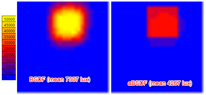
I have a problem with the aBSDF function. Trying to model a glass with a BSDF distribution, I have compared the result using BSDF and aBSDF object.
Even if the aBSDF show rendering with a better viewing of shadows, the mean lighting of the zone is significatively lower (until 40% less) than the results with BSDF. Comparing with a classic glass with equivalent transmission, it seems than the problem come from the aBSDF model.
Do you know where this difference can come from ?
I tried to understand the source code, and the compute_through function specific to aBSDF. I’m not sure to understand correctly the strategy with the near peak areas but I wonder if we shouldn’t use vpeak + vsum in the cthru attribution unlik only vpeak.
There are certainly differences in how the transmission is computed between BSDF and aBSDF, and some assumptions that must be met for correct behavior.
The problem could be associated with your XML file. How was it created? Is it a Klems representation or a tensor tree? Can you post it somewhere, and describe what you believe is an equivalent glass material?
For the equivalent glass material, I just take the transmitance given by the BSDF viewer at the incidence angle and calculate the transmitivity for glass object. The idee was just to czalculate the mean light level in the floor of the room.
Not sure I can acces to this source, I’m going to do my best.
In all cases, even if the conditions are not standard enough to represent the correct light distribution, it shoult at least respect the energy conservation and keep the same mean light level entering the room, isn’t it ?
The Klems distribution you are using does not provide enough resolution to reliably determine whether there is a peak or not, so you should only apply the aBSDF type if you know in fact that the material you are working with has a strong “vision” component – a peak in the through direction. If it scatters light significantly, as seems to be happening in your XML data, then you are better off using the regular BSDF type. If you started from high-resolution tensor tree, this decision would be less of an issue, as the peak extraction should work more reliably with detailed data.
Yes, the peak extraction method necessarily must ignore near-peak radiation to avoid double-counting. This is tricky to do, but may be improved if you compute a higher-resolution tensor-tree.
In any case, if you like the result you get from a regular BSDF, then you should have no need of the aBSDF type, which is there to help with highly peaked distributions. BSDFs with soft peaks might be handled better with the BSDF type.
The basic test is, if you can see through the material and recognize things on the other side, then the aBSDF type will probably work better. If things are blurred or distorted by the material, then the BSDF type is probably best.
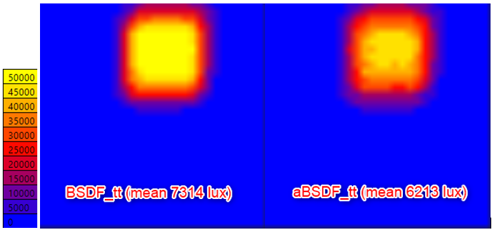
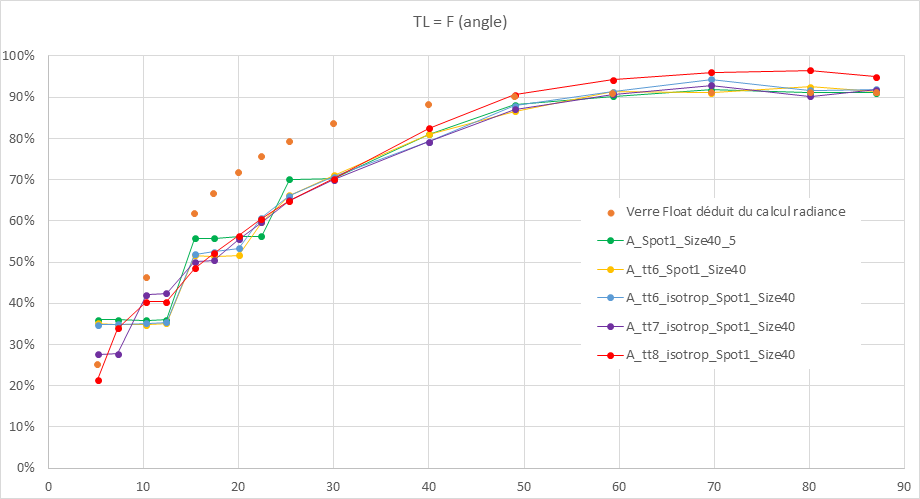
I followed your advice and try to increase the tensor tree resolution. The result is coherent and with higher resolution, both calculation (BSDF and aBSFD) give the same result. I thing that increasing the resolution, no more peak are detected and both calculation are done with BSDF algorithm.
But, trying the same comparison with another glass, less diffusing, the result are not consistent. Higher is the resolution, lower is the mean transmitted value.
The two glasses are not significantly different, so I can’t explain why the behaviour is reversed.
I downloaded your XML files, but I’m having trouble telling which file belongs to which material. Looking at the first few lines of each, they seem to be generated from different Radiance scene descriptions. For example, I would expect “win2_tt.xml” and “win2_tt6.xml” to be created from the same input file, but the former is created from “AlbaT.rad” and the latter from “B.rad”. The other files show similar discrepancies.
Comparing the actual distributions, the aforementioned pair seems similar, whereas win_tt.xml and win_tt6.xml, created from “AlbaS.rad” and “A.rad”, respectively, seem quite different. It is as if they are completely different materials, not just different resolutions of the same material.
Finally, there appears to be some light leakage near grazing angles. You specify the same bounding box for genBSDF in each case, which is “-dim 4.0 16.0 4.0 16.0 -3.901 0”. You need to be sure that the Z dimension is tightly bound. If you allow space between the back of your material and the minimum Z value, or the front of the material and the maximum Z, your results will be incorrect. Similarly, you want the minimum and maximum X and Y values to be inside the bounds of the material you have modeled, or leakage will occur.
The file name is different, but it should be the same scene. I will ask my provider to double check that.
You said that the “win” file seem quite different. I look at the global aspect with BSDF viewer and I don’t see big difference, can you tell me witch criteria change from one file to another?
I’m going to check the parameters given in your answer, but even if the xml file need to be corrected on some point, the thing I can’t understand is the difference seen for aBSDF model compared with BSDF. How is it possible to lose 30 to 40% of the mean light transmission?
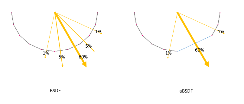
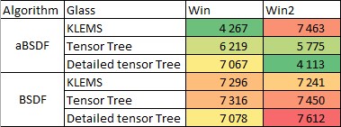
Yeah, I think the bottom line is that you have a good example of what NOT to use the aBSDF type for. The aBSDF type is really for systems like venetian blinds or woven fabric shades that have a definite “view” component to them. All of your examples have some degree of scattering in the through direction, making the application of peak extraction unreliable. In your example with the win2 material, the aBSDF is using the peak transmission value to determine the direct component, and underestimating its value because much of the light transfers near the through direction, not in the through direction. Peak extraction gives you a reasonable result with the low-resolution Klems representation more by luck than anything else, because the spread is large, but not so large as to spill over into neighboring direction cells when you have just 145 of them. The tensor tree at your lower resolution still divides the hemisphere into 1024 directions.
Ok understood.
Thank you very much for the time taken on my problem. I will try to increase the resolution and to properly select the parameters in BSDF. The calculation time will be longer, but the results should be sufficiently reliable.
I need your help again. I switched back to a BSDF representation and managed to find a satisfactory setting. However, I have problems with low angles due to the steps obtained in this location during generation.
To make these steps disappear, I had to increase the resolution with the -c and -t3 parameters, but to limit the size of the files, I switched to an isotropic format because my model is suitable for it. However, I find instability on the near normal angles that I don’t understand. I would like to check the result of genBSDF, but since the BSDFviewer does not work with isotropic formats, I am unable to perform this check.
I saw that there are bsdf2rad and bsdfview tools, but with my version of radiance on windows, I don’t have them available. how to have access to these functions?
Both bsdf2rad and bsdfview should work under Windows. You may need a Perl interpreter, but I think our current installer even compiles the Perl scripts, so that isn’t necessary. What happens when you enter “bsdf2rad” on the command line?
I don’t have a Windows box, so it’s difficult for me to test these things out, but they are in the build code.
If I try tu run bsdf2rad I have the message “‘bsdf2rad’ is not recognized as an internal or external command, operable program or batch file’”
I can run bsdf view, and it open a rvu windows, but I have the same message about bsdf2rad :"‘bsdf2rad’ is not recognized as an internal or external command, operable program or batch file’".
Il the radiance folder, I can’t find any file named bsdf2rad… (neither a perl script)
My apologies. I see now that bsdf2rad was missing from the default target list for cmake. I have added it in. Hopefully, the automatic builds will then put it in the new alpha version package over the weekend. I’m not sure when this happens, exactly, but it should be on github by Monday.