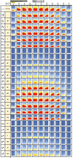
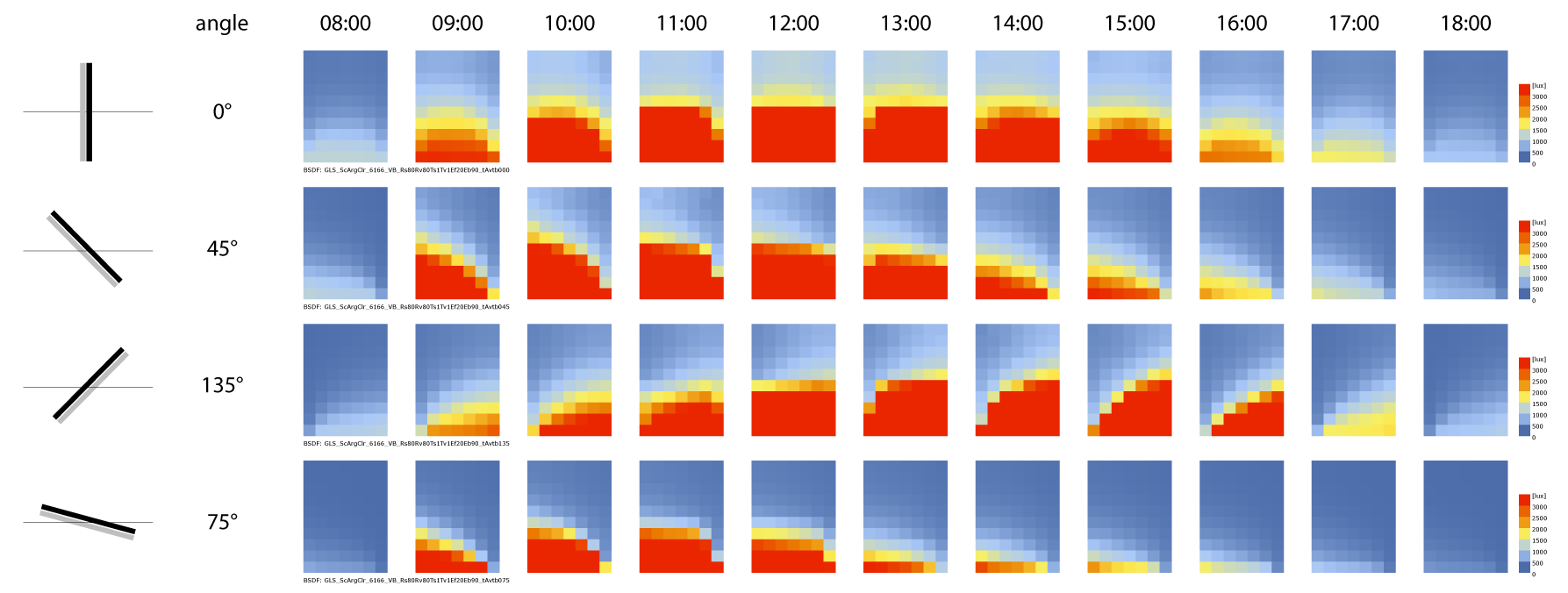
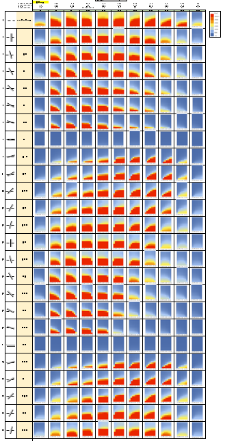
I’m trying to simulate interior vertical blinds for an office room with one big window in the south façade. I use the three-phase method and made BSDFs with the software WINDOW. I have doubts about my results. I made a big table with the illumination for different hours and different slat angles on a sunny, clear day.
My expectation is that the pattern which happens when the slat angles remains the same but the time varies, would also happens in case the hours stays the same but the slat angle would vary. My results don’t confirm this. Is my expectation not correct or are my results not correct?
I hope someone could and would help me, because I don’t know how to get this clear for myself.
My files for the script, if necessary, are in this link:
Looking at your results and your BSDFs, it seems that maybe your blind
angles aren’t how you think they are.
For example, the 90 and 270 degree results and BSDF file seem to have the
blind slats closed (vertical) instead of horizontal. In the attached excel
file, I’ve added a column of how I’d guess the blinds are oriented based on
the BSDF file and the results.
Also, you BSDFs seem to be rotated 90° in the plane of the window. But I
don’t see the effect in your results, so your model must also have the BSDF
rotated as well. It’s all good if it’s consistent, but int not
conventional. If you generated BSDFs of blinds from Window, they wouldn’t
work in this setup.
Unfortunately I can’t open your rhino/grashopper/honeybee model to verify
any of this, maybe someone else can.
Andy
(Attachment Simulation_result_VB_18_april_amcomment.xlsx is missing)
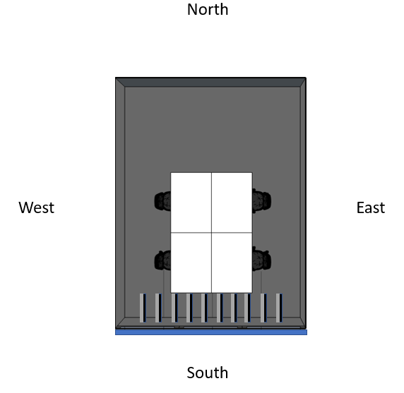
Thank you so much for your answer. My intention is, in case of for example 0 degrees, to simulate the slats perpendicular to the window. For example as in the image I quickly made. So, I did this wrong? I don’t completely understand what I simulated now, in stead of the situation I’d like to simulate.
Hi Kim,
Looking back I see that you intended vertical blinds, and that I misinterpreted your diagrams. The BSDF files look correct now that I understand. However the results look like your blinds are applied horizontally to the window. Maybe check the up vector for your window surface in the scene files. Or if you can send me the Radiance files I can look.
Best,
Andy
Information about the window orientation is provided in the #@rfluxmtx line. specifically the u=-1.0,0.0,0.0
part sets the up direction for the BSDF. This is basically making it so that the up direction of your BSDF points in the -X direction, turning your vertical blinds into horizontal blinds. I think this should be u=0,0,1 for your model and BSDFs. If you can find a way to change this in honeybee I think it’ll fix your issue.
Thank you so so much for your respons Andrew and Mostapha. It means a lot to me.
I changed the vector into (0,0,1) for all the angles, but that gave me not another answer.
Or do I have to change the vector for each state separately so that the vector is perpendicular in relation the angle or the slats?
@mostapha, what would you do to change the blinds from horizontal into vertical blinds? Maybe, I do something wrong.
I also simulated rollerblinds and also for this simulation, the u = -1.0,0.0,0.0.
Maybe honeybee reuses coefficient matrices if they already exist? I’d
suggest removing everything in the tmp and result directories and then
running.
Andy
I cannot open your full simulation folder on dropbox anymore. I see that in one of your old models however the surface normal of the window is pointing to the exterior of the space. It should face the interior.
I would check this in your current model. The vertices describing your window surfaces in Radiance follow a right hand coordinate system, meaning that the order in which vertices are noted in the Radiance polygon determine direction of the surface normal (the one below is pointing out of your space).
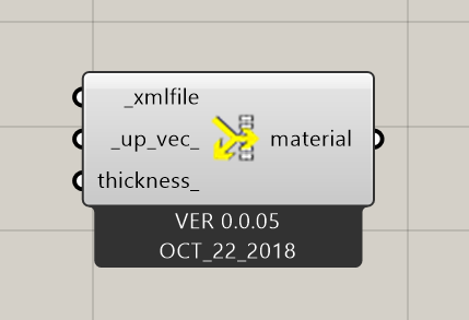
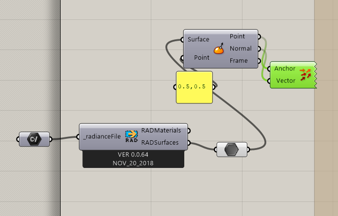
You should also be able to check this with Honeybee. Open the .rad file containing the window and remake this example definition to display the vector.
This is how it should be. HB takes care of it.
As @Mostapha said in here: “Honeybee keeps the windows looking outwards which is what we need for energy simulation. It then creates a separate file for each window group/light-source for each state and calculates the view and sky matrices for each of them separately. That’s when it flips the direction of the surfaces.”
Ok; thanks for pointing this out. What I see in an old simulation folder of @Kim is a .rad file with a window with the normal pointing out. Now that I look at Andrew_McNiel’s post I see that the surface normal is correct in this model. Sorry for the confusion.
Thank you all so much for your time and your advice.
For my own knowledge, I made some BSDFs for horizontal vertical blinds and used these in my script. The results confused me, because it gave me results I would expect for vertical blinds.
It was just a quick experiment.
I’ll keep you posted
I think there’s still something wrong with the up vector. Can you check in the VB_window.glw.rad file to see what up vector is written in the file after your change in honeybee?
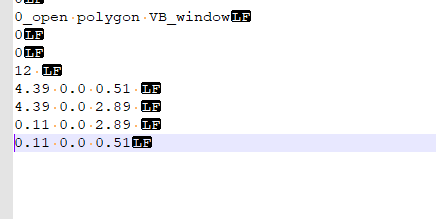
I think the suggestion by @Andrew_McNeil about the vector in the file VB_window.glw is correct. If I’m not mistaken, setting the up vector for the BSDF in Honeybee will only affect the BSDF material itself and not the above mentioned file. Below is part of the output from the file VB_window…default.rad when I apply a vector (0, 0, 1) to the BSDF material component:
Now, back to the file VB_window.glw. I don’t know how Honeybee decides the vector in this file. However, I extracted the four points of the window surface and recreated it as seen below in the image.
These results are so much more in line with my expectations.
Thank you all so much for your time and sharing you knowledge with me.
I don’t know if I could solve this alone, definitely not in this short time.