Pmap ooc vs Radiance Classic

Dear Radiance community,

First of all, I would like to begin by congratulating the great team behind setting up the discourse pages. It is soooo much better than the old mailing lists !!

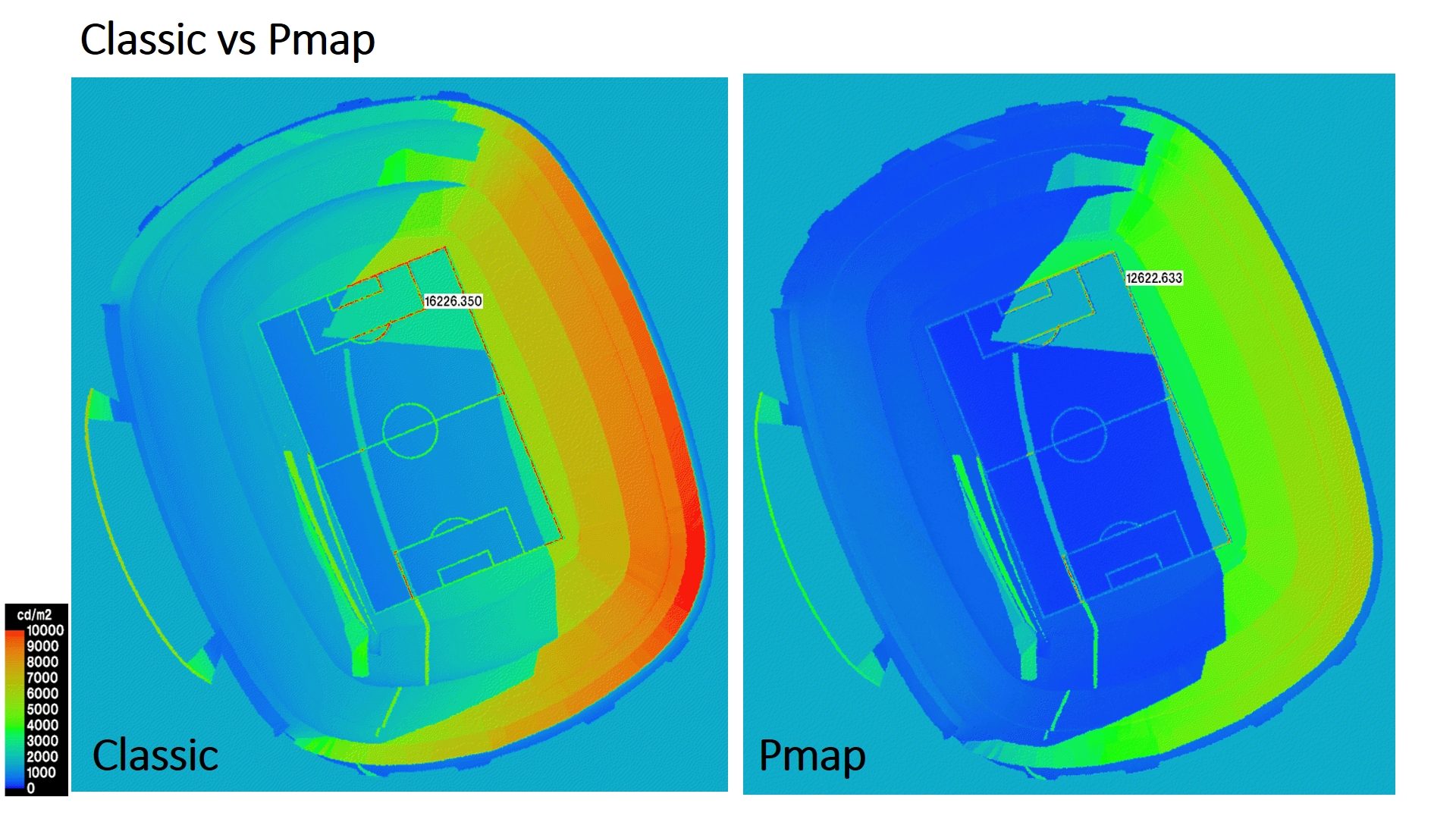
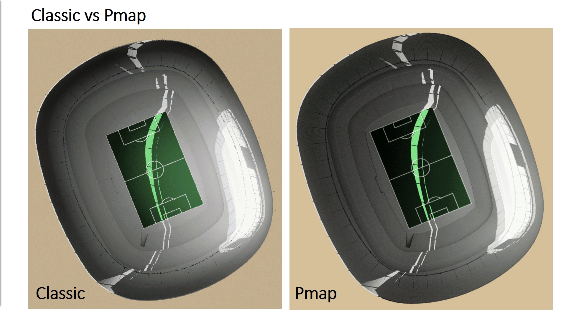
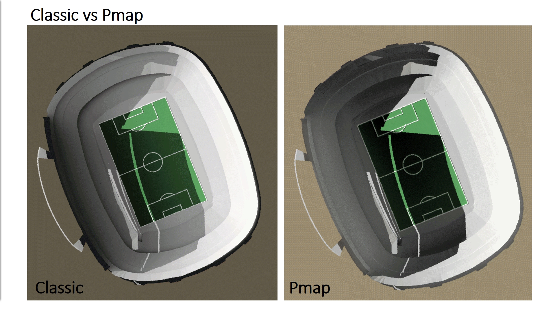
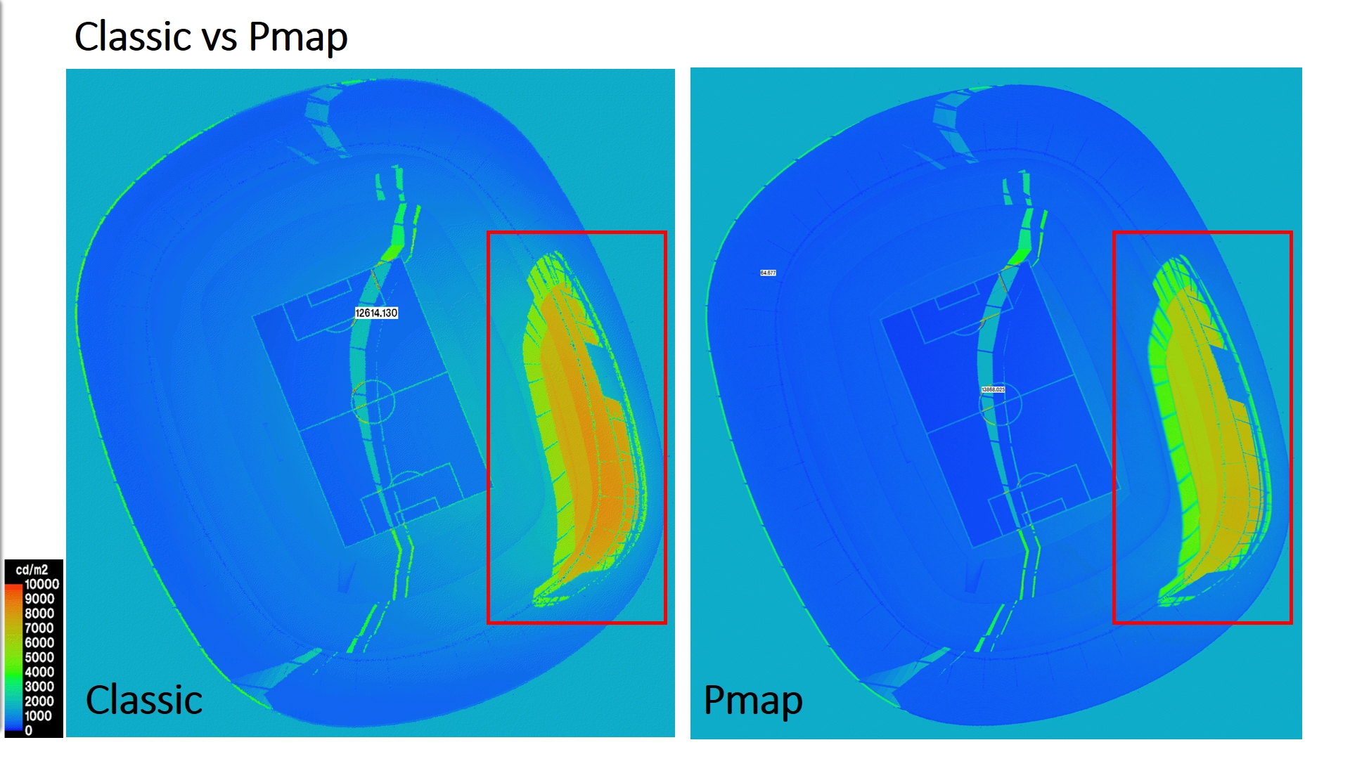
That being said, a while ago I was working quite intensively with Photon Mapping in radiance. I simulated a couple of test cases with pmap but when I compared the results with classic Radiance, I found some discrepancies which I could not fully explain. The luminance values from photon mapping were always lower compared to what I got from radiance classic. I am posting the two cases below:

I used Radiance 5.1 on a Linux machine with 30 processors for all simulations. These were my settings:


[ Radiance Classic ]

rpict -vf 05_31_18_Top_TS_0.vf -af ./05_31_18.amb -t 30 -ps 1 -pt 0.05 -pj 1 -dj 0 -ds 0.02 -dt 0 -dc 0.75 -dr 0 -dp 64 -st 0.85 -ab 8 -ad 8192 -as 4096 -ar 1200 -aa 0.100 -lr 18 -lw 0.050 ./05_31_18_IMG.oct > 05_31_18_0.unf

I then delete the .unf file from last step, and then run the following for Overture:

rpict -vf 05_31_18_Top_TS_0.vf -af ./05_31_18.amb -t 30 -ps 1 -pt 0.05 -pj 1 -dj 0 -ds 0.02 -dt 0 -dc 0.75 -dr 0 -dp 64 -st 0.85 -ab 8 -ad 8192 -as 4096 -ar 1200 -aa 0.100 -lr 18 -lw 0.050 ./05_31_18_IMG.oct > ./05_31_18_0.unf

pfilt -1 -r .6 -x/2 -y/2 ./05_31_18_0.unf > ./05_31_18_0.HDR


[ PMAP Radiance with ooc ]

I first create a global Pmap with 1000M global photons (it was a big project):

mkpmap -n 30 -apg 05_21_18_g1000M.gpm 1000M -apD 0.1 -dp 1000 -ds 0.02 -t 10 05_21_18_g1000M_RAD.oct

Then I run rpict with a global photon lookup radius of 600

rpict -vf Top_TS_Top_TS_0.vf -t 10 -ab -1 -ad 4096 -ar 0 -aa 0.1 -ps 1 -pt 0.05 -pj 1 -dj 0 -ds 0.02 -dt 0 -dc 0.75 -dr 0 -dp 64 -st 0.85 -lr 8 -lw 0.050 -ac 8 -aC 1M -ap ./05_21_18_g1000M.gpm 600 ./05_21_18_g1000M_RAD.oct > ./Top_TS_gBW600_0.unf

pfilt -1 -r .6 -x/2 -y/2 ./Top_TS_gBW600_0.unf > ./Top_TS_gBW600_0.HDR


I don’t understand why the luminance from the image in Pmap is less compared to the one from Radiance classic? I wonder what I am doing wrong… Any hints / explanations regarding this would be really helpful.

@Dr_Roland_Schregle

Here’s another study, which shows much greater difference:


[Radiance Classic]

rpict -vf 05_31_18_Top_TS_0.vf -af ./05_31_18.amb -t 30 -ps 1 -pt 0.05 -pj 1 -dj 0 -ds 0.02 -dt 0 -dc 0.75 -dr 0 -dp 64 -st 0.85 -ab 6 -ad 2048 -as 1024 -ar 600 -aa 0.100 -lr 18 -lw 0.050 ./05_31_18_IMG.oct > ./05_31_18_0.unf

Delete the .unf file from last step, and then run the following for Overture:

rpict -vf 05_31_18_Top_TS_0.vf -af ./05_31_18.amb -t 30 -ps 1 -pt 0.05 -pj 1 -dj 0 -ds 0.02 -dt 0 -dc 0.75 -dr 0 -dp 64 -st 0.85 -ab 6 -ad 2048 -as 1024 -ar 600 -aa 0.100 -lr 18 -lw 0.050 ./05_31_18_IMG.oct > ./05_31_18_0.unf

pfilt -1 -r .6 -x/2 -y/2 ./05_31_18_0.unf > ./05_31_18_0.HDR


[ PMAP Radiance with ooc ]

Create a global Pmap with 1000M global photons:

mkpmap -n 30 -apg 05_31_18_g1000M.gpm 1000M -apD 0.1 -dp 1000 -ds 0.02 -t 10 05_31_18_g1000M_RAD.oct

Run rpict with a global photon lookup radius of 600

rpict -vf Top_TS_Top_TS_0.vf -t 10 -ab -1 -ad 4096 -ar 0 -aa 0.1 -ps 1 -pt 0.05 -pj 1 -dj 0 -ds 0.02 -dt 0 -dc 0.75 -dr 0 -dp 64 -st 0.85 -lr 8 -lw 0.050 -ac 8 -aC 1M -ap ./05_31_18_g1000M.gpm 600 ./05_31_18_g1000M_RAD.oct > ./Top_TS_gBW600_0.unf

pfilt -1 -r .6 -x/2 -y/2 ./Top_TS_gBW600_0.unf > ./Top_TS_gBW600_0.HDR


Can you tell us a little more about your model(s)? I assume there is some sort of roof structure – is there any glazing? If so, what happens if you run the simulations without the glazing?

Thanks for your swift reply Greg.

Apologies I didn’t tell much about the geometry. So these were 2 stadiums - one with a roof and the second without. No glazings. All materials were plastic, including all seating bowls, roof etc except for a very small “ring” of a translucent glass material in the stadium with a roof.

I am sharing the true colour renders below, in which one can’t really tell the difference:

If you think sharing the rad / oct files may help, I’ll be more than happy to do so.

Here’s the second stadium (sorry couldn’t post it with the previous thread, discourse won’t let me post 2 images in a thread on account of me being a new user to the forum)

Hi Mohammad,

thanks for posting these details. These parameters look ok, though I’m
wondering whether you need the -dp and -ds parameters for mkpmap; this
would make sense if you are using a local light source with a specified
luminance distribution, which I assume isn’t the case here. Either way, it
should not cause the discrepancies. Btw, mkpmap also understands a ‘g’
multiplier, so you can conveniently specify 1g instead of 1000m.

Could you clarify what kind of material you defined for the illuminated
portion of the stadium, and whether this patch is lit directly or via an
intervening bounce or transmission?

Many thanks and best regards,

–Roland

Hi Roland,

Thanks for your swift response. Hope you’re doing well.

Understood. Didn’t realise that.

That’s so handy. Good to know!

Below is a list of all materials used. I realised later that I indeed had a glass material, contrary to what I wrote earlier in my reply to Greg earlier.


void glass glass80
0
0
4 0.872 0.872 0.872 1.520

void plastic SIDE_GROUND
0
0
5 0.569 0.569 0.569 0.000 0.000

void plastic bowl50
0
0
5 0.500 0.500 0.500 0.000 0.050

void plastic opaque90
0
0
5 0.900 0.900 0.900 0.000 0.050

void plastic Pitch_Line
0
0
5 1.000 1.000 1.000 0.000 0.000

void plastic Pitch
0
0
5 0.094 0.329 0.106 0.000 0.200

void plastic ref35
0
0
5 0.350 0.350 0.350 0.000 0.050


The following cross-section should help explain the geometry & materials better:

If you need any additional information, I will be more than happy to provide that.

Regards,
Hamza

Hi Mohammad,

thanks for the material params, I understand there are no specular surfaces other than the glass, right? There are issues with photon map and directly visible specular highlights, but I’m ruling this out here. I suggest you compare irradiance renderings (with rpict’s -i option) to disregard the material properties. Also, is there a particular reason why you are using different octrees for Classic and Pmap? I assume this is not a source of deviations.

Looking at your rpict parameters, I noticed your specular threshold -st is too high (though it shouldn’t matter here anyway), and likewise your -lw in conjunction with a high number of ambient bounces. I suggest you either lower these parameters substantially or omit them entirely and go with the defaults.

From the mkpmap parameters, I understand you are not using photon ports; your simulations must take aeons. I suspect a huge number of photons are being deposited outside the stadium due to interreflection from the ground plane. I’m not ruling out a possible counter overflow under these circumstances, since the emitted number of photons must be huge (and as you say, it’s a big project).

I suggest you specify your glass material as a photon port (assuming the normals are facing inwards), and create another one of antimatter material that covers the stadium aperture. You will also need additional antimatter ports along the perimeter of the stadium behind the top row seats. This complicates your model but should dramatically accelerate your simulation, and you can use the same model for Classic without side-effects. I’d be interested in seeing how this affects the results; infact, it shouldn’t.

Let me know how that works out. Right now I’m as stumped as you are. :confused:

Best regards,

–Roland