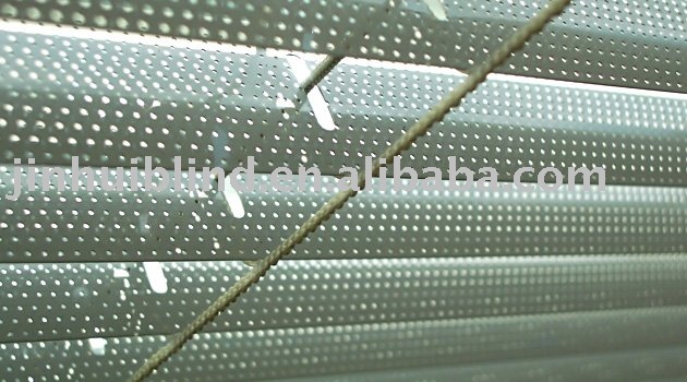
I'm doing a daylighting analysis of different facade configurations, and
the architect is looking at perforated blinds shading, similar to i.e. this
google image I found;
I'm doing a daylighting analysis of different facade configurations, and
the architect is looking at perforated blinds shading, similar to i.e.
this google image I found;
Is there any guidance or method to model this concept? Any references
you could point me too?
1) If you can ignore the fact that the perforation leads to a
transmission not uniformly spread over the blind's surface, but
concentrated on the holes, you could use a trans modifier.
2) If you want to consider the pattern created by the perforation (if
you would look at it from very close distance), you can use mixfunc to
vary between the reflective surface (metal) and the transmissive holes
(void). You would need a procedural description of the perforation.
Yes, in this case I can comfortably assume that the transmission is uniform
over the surface and will use the trans modifier. My question is, what
transmissivity should I use? If I assume that the void space is 15% of the
area, how shall I define the trans modifier? Is it actually reasonable then
to simply assume transmissivity=85%? We have done this, and the lux values
are lower than expected. What about the transmittedSpecular value?
Are there i.e. any empirical correlations for equivalent transmissivity as
a function of hole size and/or void area ratio?
Thanks again for the feedback!
Marcus
···
--
Marcus Jones, M.Sc., LEED®AP BD+C
*Freelance energy consultant*
*Vienna, Austria*
On Wed, Feb 22, 2012 at 11:55 AM, Lars O. Grobe <[email protected]> wrote:
Hi Marcus!
> I'm doing a daylighting analysis of different facade configurations, and
> the architect is looking at perforated blinds shading, similar to i.e.
> this google image I found;
>
> http://i01.i.aliimg.com/photo/v0/299829755/perforated_aluminum_blind.jpg
>
> Is there any guidance or method to model this concept? Any references
> you could point me too?
1) If you can ignore the fact that the perforation leads to a
transmission not uniformly spread over the blind's surface, but
concentrated on the holes, you could use a trans modifier.
2) If you want to consider the pattern created by the perforation (if
you would look at it from very close distance), you can use mixfunc to
vary between the reflective surface (metal) and the transmissive holes
(void). You would need a procedural description of the perforation.
Your LUX values will be very low. With a trans material you are basically
reducing the incoming light to about 1/8th of the available light. Your
simple trans material will also not account for indirect light reflected
off the blinds. This can be a substantial part of the transmitted light.
What about the transmittedSpecular value?
The transmittedSpecular part can be left at 1 (100%) because the light
passing through the holes will not be modulated. As a result you should see
the projection of the window opening on the floor if direct sunlight hits
it, just as you would see the shape of the window drawn in tiny dots in
real life. With trans you will not be able to model the angular dependent
cut off that you get with small perforated panels.
Are there i.e. any empirical correlations for equivalent transmissivity as
a function of hole size and/or void area ratio?
Unfortunately there is no golden rule because every system is different.
You have to look at the system and model it's shading effects as best as
possible. Sometimes this needs more than one calculation:
You could, for example, use your trans material to model only the light
that passes through the holes. Then you model another scene with metal
blinds in their actual size (or perhaps a bit larger) to capture the
indirect reflected light. Add both results together and you have a
reasonable approximation of the real system.
Your LUX values will be very low. With a trans material you are
basically reducing the incoming light to about 1/8th of the available
light. Your simple trans material will also not account for indirect
light reflected off the blinds. This can be a substantial part of the
transmitted light.
I was assuming that the blinds are still modelled geometrically (e.g.
using genblinds or an imported mesh). The trans modifier was just
proposed to be applied to the blinds geometry. As the (metal?) blinds
are transmissive only due to the holes, transmission would be purely
specular, reflection probably both diffuse and specular.
It's really hard to tell from a single photograph, but it looks like your reflectance is probably around 50% gray with some fraction of that specular. Here is my guess at a trans material for the slats:
The 0.15 value is my guess at the roughness. This material will have 15% specular transmission (.65*(1-.2)*.29*1), 20% specular reflectance, and 37% diffuse reflectance (.65*(1-.2)*(1-.29)). Unfortunately, the math of the trans type is difficult to follow, which is why most folks use a spreadsheet or refer to the Lighting chapter in RwR.
If you arrange your slats into the correct blinds geometry, you can generate a BSDF for the system using genBSDF. I should warn you though, there is a bug in the 4.1 release of genBSDF. I'm waiting for Rob G. to finish his Windows package before I post a patch.
Best,
-Greg
···
From: Marcus <[email protected]>
Date: February 22, 2012 3:56:24 AM PST
Thanks for your response Lars,
Yes, in this case I can comfortably assume that the transmission is uniform over the surface and will use the trans modifier. My question is, what transmissivity should I use? If I assume that the void space is 15% of the area, how shall I define the trans modifier? Is it actually reasonable then to simply assume transmissivity=85%? We have done this, and the lux values are lower than expected. What about the transmittedSpecular value?
Are there i.e. any empirical correlations for equivalent transmissivity as a function of hole size and/or void area ratio?
If you arrange your slats into the correct blinds geometry, you can generate a BSDF for the system using genBSDF. I should warn you though, there is a bug in the 4.1 release of genBSDF. I'm waiting for Rob G. to finish his Windows package before I post a patch.
Unfortunately that has been held up in contracts, as we are hiring Kitware to help us wrap up the last bits. I had hoped we'd have that in place by now, but I'm covered in red tape. =8-/
I will poke them again. Once the thing is in place, I expect it would be a matter of days to finish the project.