Not recognized as fish eye image

An image taken with a fisheye lens is not recognized as a fisheye image. Does anyone know a solution?

I was able to produce HDR images from images taken at different exposure times in order to obtain DGP from the captured images.

However, when I tried to find DGP from the created image, the part outside the circle was also recognized as part of the circle like the attached image, and I could not get the correct result.

Does anyone know what to do to evaluate only the circular part taken with a fisheye lens?

By the way, DGP was calculated using Honeybee, a plugin to grassshopper, and a component called Glare Analysis.

This is the image.

Hi Keisuke,

There are a few steps to correctly preparing an HDR photograph for glare analysis. I’m not sure that you can do all of it in Honeybee, and I’d recommend you take a moment to learn batch or shell scripting to get it done correctly.

1. Crop and scale the image

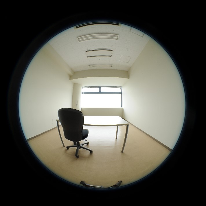
You need to trim the image to a box that is tight to the edge of the view. Let’s say the upper left corner of that box has coordinates (121, 130) and the size of the box is w=h=2043, and you want an image with w=h=1024. Then your command looks like this:

pcompos -x 2043 -y 2043 =-+ source_image.hdr -121 130 | pcomb -x 1024 -y 1024 > destination_image.hdr

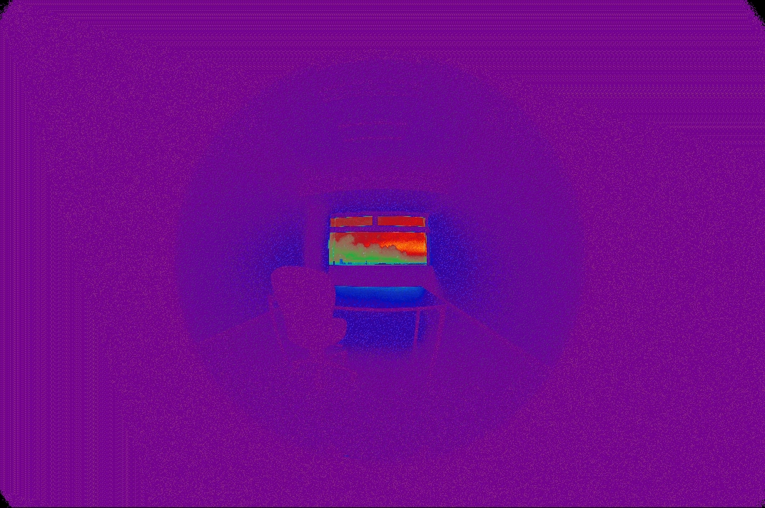
2. Remove the vignette

You’ll notice that the lens optics cause the image to become dimmer (and slightly blue) around the edge. This effect is called the vignette, and it can affect the measurement of glare sources near the image periphery. In “Comparison of the Vignetting Effects of Two Identical Fisheye Lenses” by Coralie Cauwerts, Magali Bodart, and Arnaud Deneyer (2012), measurements are presented that can be used to remove the vignette. For example, here is my .cal script for the Canon EOS 5D Mark II camera with Sigma 8 fisheye lens with f/4.0 based on their measurements (all camera and lens models will be different).

ro=ri(1)*b; go=gi(1)*b; bo=bi(1)*b; b=if(1-f,1/(-10.416*f^3+22.24*fr^5-17.324*f^2+5.4708*fr^3-0.4415*f-0.0379*fr+1),0); fr=sqrt(f); f=((x-r)^2+(y-r)^2)/(r^2); r=xres/2;

Used in context, the above command would become:

pcompos -x 2043 -y 2043 =-+ source_image.hdr -121 130 | pcomb -x 1024 -y 1024 -f vignette.cal > destination_image.hdr

3. Remove lens distortion

Glare measurements assume that fisheye images use equiangular projection. However, real fisheye lenses are not perfectly equiangular. I don’t know of an easy way to solve this, and my approach has been to measure the lens distortion by taking a picture of a test setup with equal angles, and then distorting the output image.

4. Add missing header information to the HDR file

Even after all of this, Radiance doesn’t “know” that the image is a fisheye image. The image settings can be fed to evalglare manually, but I don’t know if Honeybee does this for you. Alternately, in the past I have prepended the final HDR file with view information (I think it needs at minimum VIEW=-vta -vv 180 -vh 180).

I hope this helps,

Nathaniel

1 Like

Nathaniel includes all the best-practice recommended steps, but the accuracy of DGP results will not be much harmed by skipping steps 2 and 3.

You do need to crop the image, and it is important to preserve the original exposure in the process. I recommend the following for step 1:

getinfo < source_img.hdr > destination_img.hdr

This extracts the header from the original image, including exposure value.

Edit the text file “destination_img.hdr” to add a line to replace any existing view with “VIEW= -a -vv 180 -vh 180” as Nathaniel recommends in his step 4. If there is no existing VIEW= line, then just add it somewhere before the last (blank) line in the file. If there is no EXPOSURE= line, add “EXPOSURE= 1” to the header, also. Then, run:

pcompos -x 2043 -y 2043 =-+ source_img.hdr -121 2130 | pfilt -1 -x 1024 -y 1024 | getinfo - >> destination_img.hdr

This applies the cropping and resizing, and appends the image data to the header you have created. I changed the y offset from 130 to 2130, because y-coordinates in Radiance are measured from the bottom of the image rather than the top. If you use ximage to select your corner points (using the ‘p’ command), it will tell you the limits. If you use Photosphere, you will need to reverse the sense of the y-axis to get the right coordinates.

The above can all be scripted with some skill and effort using Perl or Python.

Best,
-Greg

1 Like

Nathaniel, Greg, thank you for kindly teaching me how to do it.

Thanks to you, I think I can advance my research to the next step.

Sorry for the late reply.
Since I was a beginner in programming, I used to learn about it by referring to Radiance manuals.

Finally, I can now manipulate Radiance directly, albeit slightly.

In fact, it wasn’t until I ran the code you gave me that I realized there was a mistake in the information I shared.

I noticed that the jpeg image I sent was already trimmed to a square and different from the rectangular image I took.

So it will be different from the coordinates you specified in pcompos.

Below are the original pictures. I’m sorry for asking you so many times, but could you tell me the new code?

Keisuke

Hi Keisuke,

The numbers in the code I gave were only examples. You would need to measure the pixel coordinates for your own image. You need the coordinates of the upper left corner of the bounding rectangle, and the width and height of the bounding rectangle, both measured in pixels.

Nathaniel

Hello Keisuke,

For more detailed information about generating and calibrating HDR image for glare analysis, I suggest you read this tutorial (open-access):

All the steps described by Nathaniel are explained in detail in it.

Hope this help!

Clotilde

Nathaniel, Clotilde thank you for your advice.

Thanks to you guys, we were able to do a lot of work.
Another question is, I use Photosphere to generate HDR images and then crop and projection adjustment, but even if I calibrate with Photosphere, I also do photometric adjustment. Is it necessary?
I don’t think it’s necessary in my expectation, but I would like to hear your opinion.

Keisuke

Hi Keisuke,

In Photosphere do you only merge the LDR images into an HDR or do you also scale your HDR image pixel values with a luminance value measured with a spot luminance meter?
If you already scale your HDR in Photosphere (with the measured luminance value), then you don’t need to do another photometric adjustment indeed.

Clotilde

Hi Pierson,

I was planning to scale the pixel value of the HDR image with the brightness value measured by the spot luminance meter in Photosphere.

Your advice was easy to understand and I was able to solve the problem.
Thank you very much.