New WGMDfunc material type

Dear All,

Just last week, I introduced a new programmable material type to Radiance 6.0a. Its design provides greater control over different components in the Ward-Geisler-Moroder-Dür model that underpins the existing plastic, metal, trans, plastic2, metal2, and trans2 material types.

The new material offers separate modifier paths for each component. This provides a convenient way to specify spectral colors using the new spectral pattern primitives, and allows different textures (surface normal perturbations) and/or patterns to apply to each.

Naturally, there are some caveats and things to watch out for, as with any material. You need to be careful that your components don’t scatter more light than they receive. More subtly, if your specular reflectance varies as a function of incident angle, this will undermine BSDF reciprocity. Reciprocity also implies that transmission should be the same from either side of the material.

------------------------ here is the new reference manual entry --------------------------

WGMDfunc is a more programmable version of trans2, with separate modifier paths and variables to control each component. (WGMD stands for Ward-Geisler-Moroder-Duer, which is the basis for this empirical model, similar to previous ones beside Ashik2.) The specification of this material is given below.

        mod WGMDfunc id
        13+ rs_mod  rs  rs_urough rs_vrough
            ts_mod  ts  ts_urough ts_vrough
            td_mod
            ux uy uz  funcfile  transform
        0
        9+  rfdif gfdif bfdif
            rbdif gbdif bbdif
            rtdif gtdif btdif
            A10 ..

The sum of specular reflectance (rs), specular transmittance (ts), diffuse reflectance (rfdif gfdif bfdif for front and rbdif gbdif bbdif for back) and diffuse transmittance (rtdif gtdif btdif) should be less than 1 for each channel.

Unique to this material, separate modifier channels are provided for each component. The main modifier is used on the diffuse reflectance, both front and back. The rs_mod modifier is used for specular reflectance. If "void" is given for rs_mod, then the specular reflection color will be white. The special "inherit" keyword may also be given, in which case specular reflectance will share the main modifier. This behavior is replicated for the specular transmittance modifier ts_mod, which also has its own independent roughness expressions. Finally, the diffuse transmittance modifier is given as td_mod, which may also be "void" or "inherit". Note that any spectra or color for specular components must be carried by the named modifier(s).

The main advantage to this material over BRTDfunc and other programmable types described below is that the specular sampling is well-defined, so that all components are fully computed.
Hi Greg,

this does indeed seem like a very flexible material type. Following up on my rollershade work this summer, it seems like the combination of functional transmittance specification plus parameterized roughness could be useful. One thing I noticed with an initial test, it seems that the NxP etc… variables are not available as they are with BRTDfunc. Should they be since this material also does not flip the surface normal? It is quite useful to have access to Idx,Idy,Idz and while I can add those to the cal file,I thought this might make sense more generally. Related, this from rayinit.cal:

For *func & *data materials, the following are also available:

NxP, NyP, NzP			- perturbed surface normal
RdotP				- perturbed ray dot product
CrP, CgP, CbP			- perturbed material color

is not strictly true as these variables are not available in, for example, mixfunc. Is it only BRTDfunc that provides these?

Another related question: As soon as a specular component has any roughness (be it in trans, trans2 or WGMDfunc) shadow rays are blocked (no patch of sun transmitted) even if ss=0 and the material otherwise appears clear. I understand that in the general case this gets intractable for backwards raytracing, but for very small roughness values that visibly scatter on the order of the sun’s solid angle, is there anyway I can manipulate settings to let the shadow ray pass unperturbed as an approximation, but still use specular sampling and a roughness for the view rays?

thanks!

-Stephen

Hi Stephen,

Good questions. I thought about setting the “perturbed” variables in WGMDfunc, but it’s a significant expense whether they are applied or not. In the other BRTDF types, this expense is incurred just once, but for WGMDfunc, it would have to be reset for every modifier chain, so it might cost four times as much. And it wouldn’t make much sense to include the CrP, CgP, and CbP settings, as a big advantage of the new material is better spectral support, and the variables only compute Y values. That said, I could easily supply an always-positive, perturbed dot product if that’s all you need. It wouldn’t be too different from abs(Rdot), though.

Out of curiousity, what do you want to use the perturbed values for?

Regarding source rays, as soon as there is a non-zero roughness, the transmitted ray goes from being a TRANS type that is included in the direct calculation to being a SPECULAR type that is thrown in with the indirect calc. Harsh, I know, but having an arbitrary cut-off didn’t make much more sense, and knowing how the scattering and source size interact is not always straightforward. If you don’t want to use a BRTDfunc, which has separate view and specular transmission, you can apply a mixfunc and combine your desired appearance material with a straight trans or glass material to provide shadow ray transmission. (Yes, it’s sad to have to lean back on mixfunc, but at least it’s an option.)

Cheers,
-Greg

P.S. I created a trial implementation that adds the NxP, NyP, NzP, and RdotP settings, and it was only about a 2% performance hit, so I guess there’s no real harm in it.

Hi Greg,

First, to your question: I don’t directly use the perturbed value, just the transformed incident vector (Idx, Idy, Idz) to calculate the effective openness when there is some phi dependence. This also serves to orient the material (with an orientation vector provided). I also use the Ldx(), Ldy(), Ldz() functions to transform the source direction into local coordinates for the directional-diffuse part. When I do this in a mixfunc, I just duplicate those lines from rayinit.cal and change the perturbed normal to the regular normal, but with a BRTDfunc i use those declarations from rayinit directly.

Regarding your suggestion to use a mixfunc to provide shadow ray transmission, how do I distinguish between shadow ray and view ray in the mixfunc?

thanks,

Stephen

PS sorry this is now quite off topic, but seems better to keep the post in context

I did go ahead and check in the change to support N{x,y,z}P and RdotP in WGMDfunc, but not C{r,g,b}P as those didn’t really make sense for this material.

Using the mixfunc with “void” as the shadow-ray-permitting part would make most sense for mesh shades, since you are trying to mimic openings. You will also be able to see through the material under some lighting conditions. The flag variables are not accessible to the .cal environment to permit one and block the other. I think the prism1 and prism2 types are the only exception, as they provide a source-direction vector that is zero for non-source rays. You might be able to mix with prism1 with a pass-through direction rather than “void” to get what you want.

Yes, we are way off topic, but that’s what makes things interesting.

-Greg

Hi Greg,

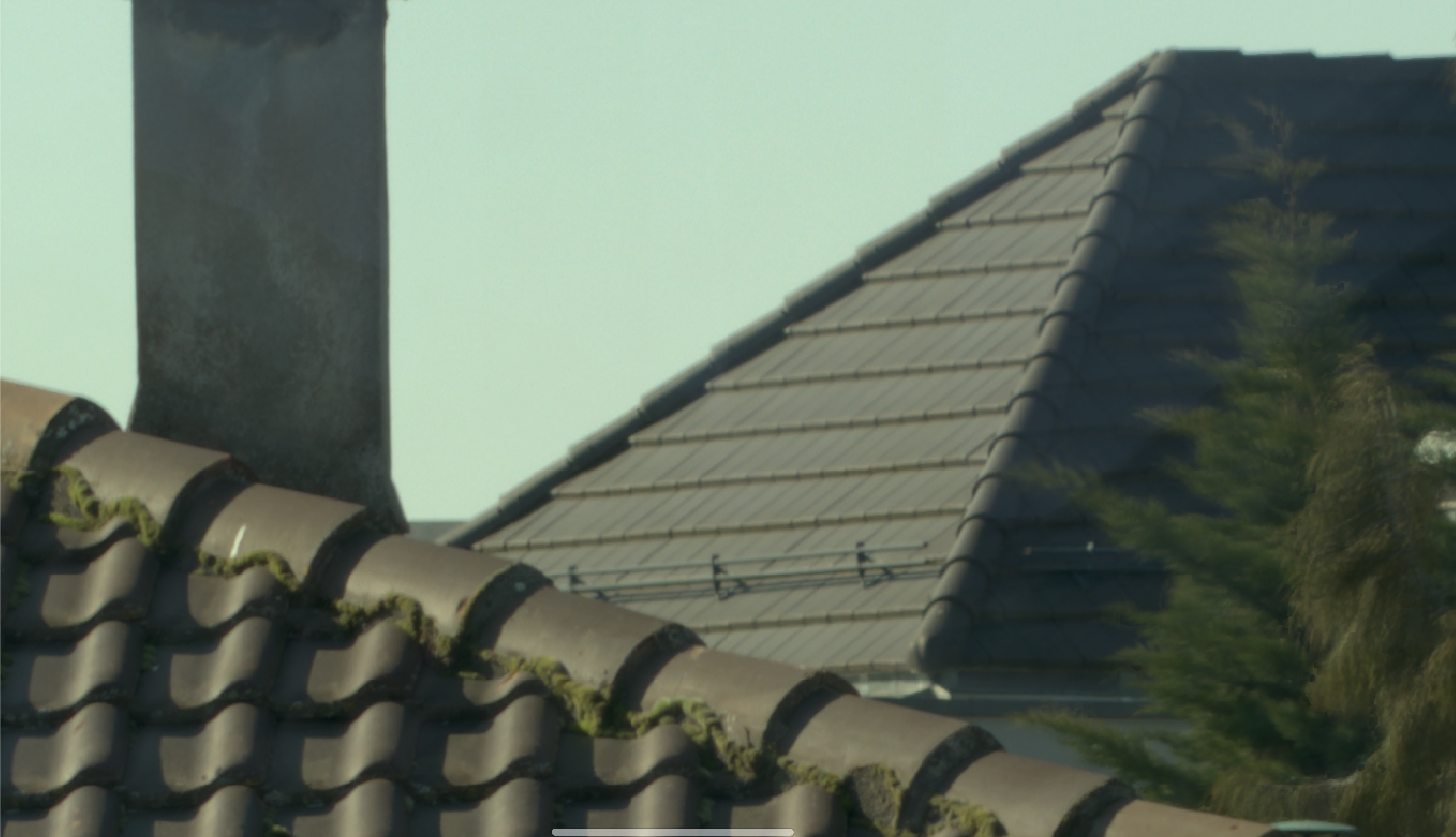
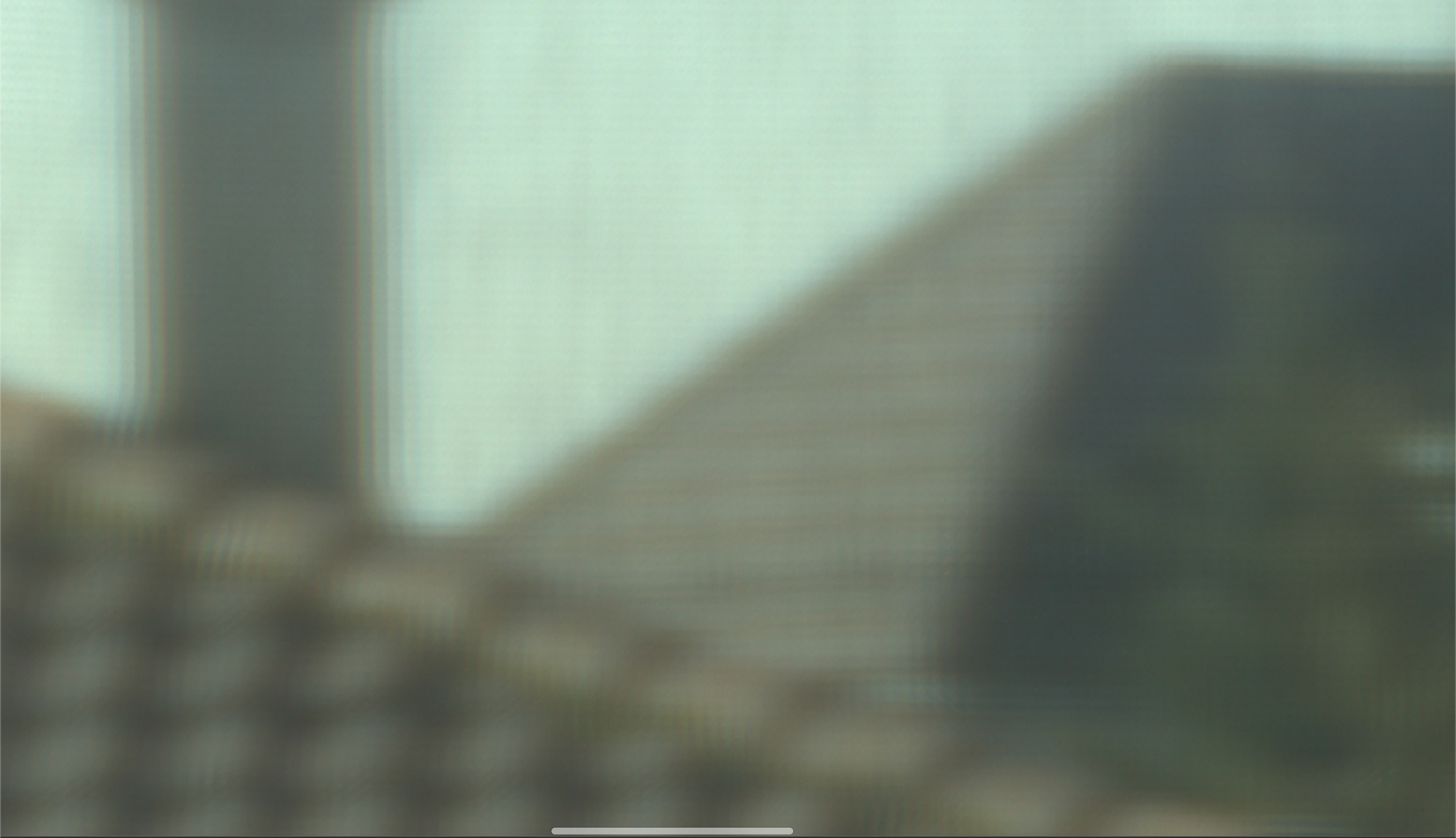
Following up on this after a while, I’m really not sure that “void” can fully capture the observed behaviour through mesh shades. Take a look at these two pictures and let me know if you agree as to what is going on:


Both images are focused on the roofs (near roof ~35 meters away) with and aperture of F-11. The first image is shot through a window, but scaled to match the brightness of the second image. The second image is shot through a black 5% openness fabric sample ~ 2.5 meters away. These images are cropped to highlight the detail, but the surrounding image confirms they are both in focus on the distant objects. To me it seems clear that the fabric is somehow blurring the image beyond. My guess is that this is due to the inner edges of the threads having a specular component which reflects near normal light through adjacent openings causing this blur. This probably is exactly the same optically as the cross pattern observed when looking at the sun through the fabric.

So, if we were modelling the fabric with 3d geometry, than a void would be correct, but once it is approximated with a single surface, the only way I see to model the correct clarity through the shade is with some scattering of the specularly transmitted light. For my immediate purposes, which had the exterior modelled with an environment map and had the only openings completed covered, I was able to simulate this by blurring the environment map (with each openness factor requiring a different blur radius). But it would be really nice if there was a way to simulate this scattering generally, without losing the direct source transmission (the issue I ran into up-thread) and the sun patches on the space. Any ideas on how to do this?

-Stephen

Hi Stephen,

This looks a bit like diffraction from all the little apertures, but it could be specular reflection off the threads as you say, or some combination.

In any case, you might try modeling it as a pure specular component with a small applied texture. The “gloss.cal” file should work for this:

{
Rough surface texture for anisotropic materials.

A1 - RMS facet slope (roughness) in x.
A2 - roughness in y.
A3 - roughness in z.
}

gloss_dx = A1*nrand(Px*.9113+Py*.3697+Pz*.4468);
gloss_dy = A2*nrand(Px*.85875+Py*.1521+Pz*.1782);
gloss_dz = A3*nrand(Px*.5992+Py*.7961+Pz*.3213);

Your A{1,2,3} parameters will be pretty small, I think. You can apply them using a texfunc modifier just to the transmitted specular component with zero roughnesses in WGMDfunc.

-Greg

thank you greg, this works!

the next challenge is to relate the dimension of the holes to the roughness parameter, especially since it seems to be directional (this fabric has holes that are tall and skinny), so the diffraction is greater in the horizontal direction. Any ideas how to translate the Airy disk radius to a reasonable approximation using the roughness parameters?

I can only advise you to experiment. The Gaussian noise used in gloss.cal may not be the right function, exactly, but I’m not sure what would be better.

I would try photographing a checkerboard angled back behind the blinds, then rotate the blinds so your two major axes are aligned with horizontal. Use the smallest aperture you can on your camera. Then, do equivalent renderings and adjust the A{1,2,3} parameters to match.

-Greg

Hi Greg,

I am investigating the use of the WGMDfunc material to simulate transparent and translucent textiles with different levels of transparency (approximately 26–65% hemispherical transmission).

I have wavelength-dependent measurements (380–780 nm) of diffuse and direct/specular reflection (front/back) and transmission. My aim is to represent these optical components independently in Radiance and evaluate their influence on indoor spectral lighting conditions, particularly melanopic EDI.

I am using LARK in Rhino/Grasshopper, which performs three RGB simulations to represent nine spectral channels. The proposed approach is to average the measured spectra within LARK’s nine wavelength bands and use these values to construct three corresponding WGMDfunc material definitions.

After reviewing the documentation, I would appreciate clarification on three points:

1. Energy conservation and front/back reflection

The documentation states that the sum of specular reflection, specular transmission, diffuse reflection (front/back), and diffuse transmission should be less than 1 per channel.

Am I correct that energy conservation should be evaluated separately for each incident side, i.e., front reflection + transmission + absorption = 1, without including back reflection in the same balance? Also, does rs apply equally to specular reflection from both sides?
I have reflective textile on both sides, and summing their reflections alone would exceed 1.

2. Roughness parameters

I understand that roughness describes angular scattering rather than the amount of transmitted/reflected light. Since I have direct/diffuse measurements but no angular BSDF data, would setting rs_urough = rs_vrough and ts_urough = ts_vrough be a reasonable initial assumption? Would zero roughness be more appropriate for the direct/specular components, with the remaining transmission represented as diffuse? What is the best way to estimate roughness?

3. Spectral input and modifiers

For LARK’s nine channels, is it appropriate to use band-averaged spectral values directly for the diffuse RGB parameters (rfdif, rbdif, rtdif)?

For specular reflection and transmission, how should I combine the scalar values (rs, ts) with their respective spectral modifiers (rs_mod, ts_mod) without incorrectly scaling the measured spectra? Would using spectrum modifiers be preferable to generating three separate RGB material definitions for the nine-channel simulation?

I am relatively new to Radiance and would appreciate any guidance on whether this is a physically appropriate approach for representing measured spectral textile properties.

Thank you very much for your help!

Best regards,
Alyaá Tabbah

Hi Alyaá,

Good questions! One at a time:

1. Energy conservation and front/back reflection

Yes, consider each incident direction independently to make sure you aren’t amplifying energy in your material. Thus, your formula should hold for every incident direction, not just every incident hemisphere. I.e., there should be no special direction that produces more energy than is incident, even though the hemispherical averages are well-behaved. Since reflection is separate per side, you’re correct that there is no need to consider the opposite reflective side for a given incident direction.

2. Roughness parameters

If you can see clearly in a reflection, or a material is transparent as far as seeing right through it (even if the transmission is low), then the roughness for those components should be 0. Anything else, you have to guesstimate. A frosted window might have a transmission roughness of 0.5 or so. A wavy glass, where you can sort of make out shapes through it, could be estimated by a roughness of 0.02 or so. You just have to play with it until it looks about right. (Roughness for reflected light is similar.).

Front and back roughness should be about the same, but this is not true for reflected roughness, which you can change via the material’s input variables.

3. Spectral input and modifiers

Band averaging works. It is not the best way to go, but basis function methods that take into account the input spectra and output sensitivities are much more complicated and probably not worth the benefit. This goes for all components, not just the diffuse ones.

The rs and ts scalars multiply the corresponding modifiers if not “void”, so yes do keep that in mind.

In general, the WGMDfunc material is designed to work directly with spectra, and will produce a more accurate calculation than LARK if you can provide more than 9 spectral bands. It will also be faster that way.

I have not worked with textile models specifically, but I encourage you to continue on this path as the WGMDfunc material is probably the best choice in this study.

Cheers,

-Greg