Lens models failures in visibility simulation for telescopes

Hello, Everyone!

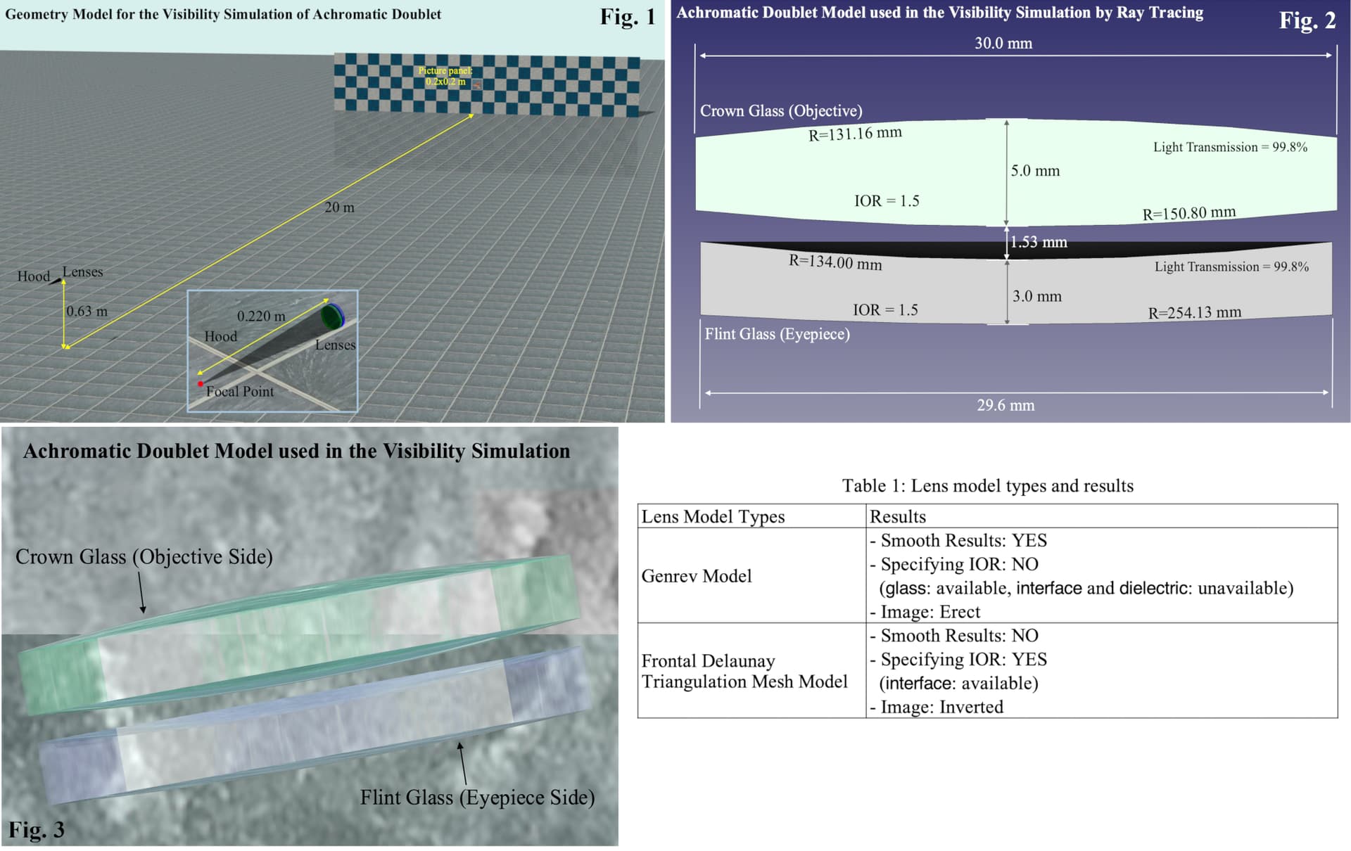
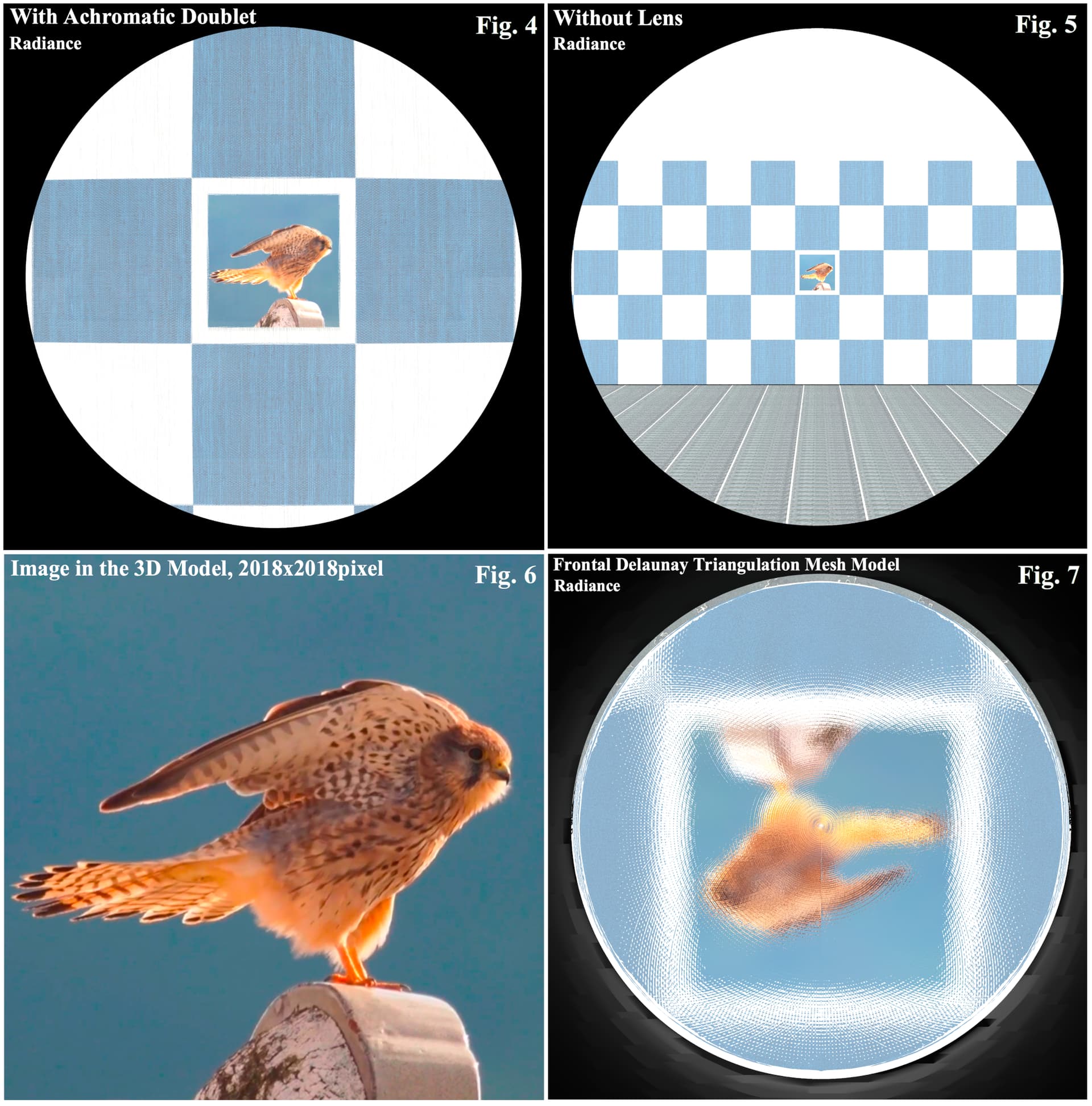
I’m studying visibility simulation for telescopes and telephoto lenses under my private project of Art & Science Collaboration and Education[1]. I have plans to simulate the visibilities caused by optical phenomena of telescopes and telephoto lenses, such as spherical aberration, distortion, and chromatic aberration. For the first step, I created a geometry model of a virtual bird watching, shown in the following Fig.1, and two achromatic doublet models, which are Radiance’s primitive model created by the ‘genrev’ command, shown in Fig. 2, Fig. 3, and Listing 1, and the Frontal Delaunay Triangulation mesh model, Listing 2, created by FreeCAD and MeshLab. Using the classic Radiance method, I calculated the image view from the lens models. However, both models have problems written in Table 1. I’d appreciate it if you give me some suggestions or advice.
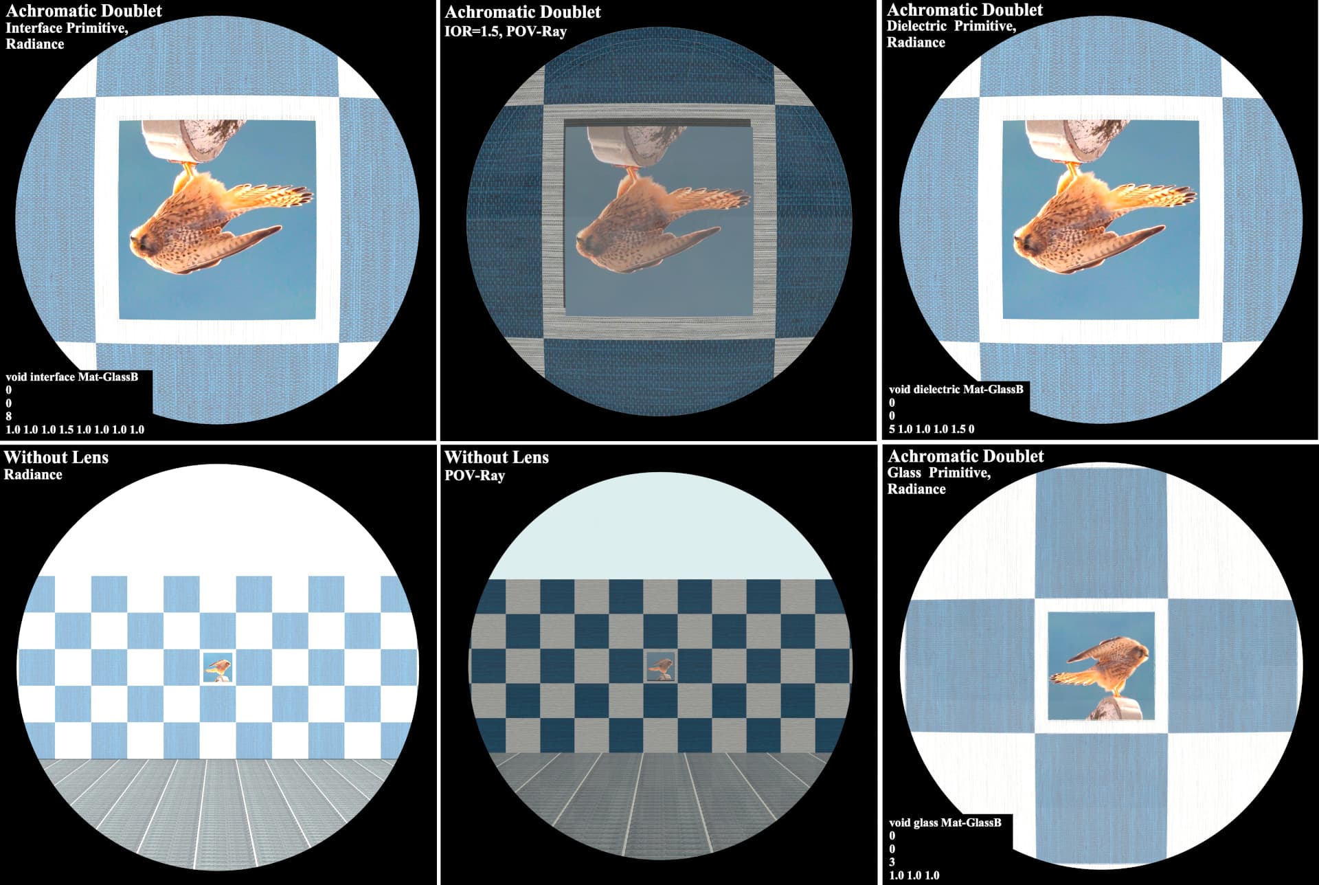
The ‘genrev’ model gave a smooth result, shown in Fig. 4 with the ‘glass’ attribute. However, it can not specify IOR, as the ‘interface,’ and ‘dielectric’ attributes gave the same failure (a magnification smaller than 1), which may be due to an incorrect normal vector direction or boundary condition. In addition, the ‘genrev’ model gave the erect image shown in Fig. 4. The Frontal Delaunay Triangulation mesh model did not give a smooth result as shown in Fig. 7 in contrast to the ‘genrev’ model as shown in Fig.4. However, the ‘interface’ attribute was available and gave considerable magnification with the inverted image.
I will share the results of this study, including analyses by POV-Ray, as a report like the previous two reports, ‘3D Design Workflow’ and ‘Photon Mapping,’ on my website[1].

-Yoichi Mizomata

[1] BEYOND THE NET: TOOLS

Listing 1: Achromatic Doublet Model by the ‘genrev’ command.

void glass Mat-GlassE
0
0
3
1.0 1.0 1.0

void glass Mat-GlassB
0
0
3
1.0 1.0 1.0

#Crown Glass (Objective)
!genrev Mat-GlassB obj-lens.01
‘0.13115966cos(0.036549115tPI)’ '0.13115966sin(0.036549115tPI)’
360 -s | xform -t 0 0 -0.1286
!genrev Mat-GlassB obj-lens.02
‘0.0016363325-t*(0.0033857641)’ ‘0.0150’ 360 -s | xform -t 0 0 0
!genrev Mat-GlassB obj-lens.03
‘-0.15080175cos(0.031771476(1-t)PI)’ '0.15080175sin(0.031771476*(1-t)*PI)’
360 -s | xform -t 0 0 0.1483

#Flint Glass (Eyepiece)
!genrev Mat-GlassE eyep-lens.01
‘0.13400914cos(0.035226075tPI)’ '0.13400914sin(0.035226075tPI)’ 360 -s
| xform -t 0 0 -0.1332
| xform -mz | xform -t 0 0 0.0023197651 | xform -t 0 0 -0.0055
!genrev Mat-GlassE eyep-lens.02
‘0.0023197651-t*(0.0033884453)’ ‘0.0148’ 360 -s | xform -t 0 0 -0.0055
!genrev Mat-GlassE eyep-lens.03
‘-0.25413401cos(0.018547905(1-t)PI)’ '0.25413401sin(0.018547905*(1-t)*PI)’ 360 -s
| xform -t 0 0 0.2526 | xform -t 0 0 -0.0055

Each glass model (Crown and Flint Glass) consists of spherical, radial, and opposite spherical parts. These three parts are discontinuous of each other, although eight significant digits were used to avoid loss of significance in differentiation calculations using trigonometric functions.

Listing 2: Data conversion from *.obj to *.rad.

obj2rad -o Glass-Poly obj-lens04.obj > obj-lens04.rad
sed -i -e ‘s/white/Mat-GlassB/g’ obj-lens04.rad
xform -n obj-lens04.rad -s 0.001 obj-lens04.rad > obj-lens04S.rad
cat obj-lens04S.rad | grep -c ‘polygon’
287026
cat obj-lens04S.rad | grep -c ‘texfunc’
91615

The number of polygons smoothed using the’ texfunc’ function was about 30% of the total polygons, less than the 90% previously done with smoothing the wine glass model reported in ‘3D Design Workflow.’


Hi Yoichi,

There’s a statement in the genrev man page that says:

When z is increasing with t, the surface normal points outward. When z is decreasing, the normal points inward.

I believe you did not follow this rule in creating your lenses, so most (all?) of the surface normals point inwards rather than outwards. A convex lens surface should be made of cones, and a convex lens surface should be made of cups, and I believe you have the opposite.

If you reverse the ordering of your parametric functions, this should resolve the problem.

I also went to the trouble of checking that the genrev smoothing option (-s) does work for a dielectric surface. There was a time when it didn’t, but I must have fixed that problem some years ago, because it seems to do the right thing. However, Radiance does not have much presence in the optical design field outside of daylighting systems, and we offer no guarantees regarding its suitability for such purposes.

Best,
-Greg

Thank you for your suggestion and advice, Greg!
As you pointed out, I did not follow the rule in the genrev manual and specified the opposite direction of normal vectors except on the concave surface of the flint glass. Then, I flipped the normal vectors by replacing t with (1-t) in the previous code, shown in Listing 3, and calculated the image view from the focal point of the achromatic doublet. Besides, I calculated the same scale model as the model of Radiance by POV-Ray, and rendered it for comparison, as shown in the following figure. In addition, I calculated the same lens model using the dielectric primitive, which gave almost the same result as the calculation using the interface primitive, and the -s option worked well. Still, the glass primitive gave small magnification, possibly due to the lens model’s surfaces are not closed. According to the scale of the model (e.g., the focal length of the lens is 220 mm) and rendered images by Radiance and POV-Ray, the distance between the focal point of the lens and the image plane for the projection behind the lens is approximately 30 mm. However, I don’t know if it is correct or incorrect since I can not find the specification about the image plane condition of Radiance. The following list is an improved code of the lens model created by the genrev command.
Note: I am trying to understand why the asterisks on the following list are disappearing, although I just pasted the code from the shell window of my mac. Please add asterisks and use as appropriate.

Listing 3: Achromatic Doublet Model by the genrev command.

void interface Mat-GlassE
0
0
8
1.0 1.0 1.0 1.5 1.0 1.0 1.0 1.0

void interface Mat-GlassB
0
0
8
1.0 1.0 1.0 1.5 1.0 1.0 1.0 1.0

##Crown Glass (Objective)
!genrev Mat-GlassB obj-lens.01 \
	'0.131159656*cos(0.0365491152227104*(1-t)*PI)'\
	'0.131159656*sin(0.0365491152227104*(1-t)*PI)'\
	360 -s | xform -t 0 0 -0.128659656
!genrev Mat-GlassB obj-lens.02 \
	'0.00163633255313365-(1-t)*(0.0033857640681837)'\
	'0.015027'\
	360 -s | xform -t 0 0 0
!genrev Mat-GlassB obj-lens.03 \
	'-0.15080175*cos(0.0317714760598272*t*PI)'\
	 '0.15080175*sin(0.0317714760598272*t*PI)'\
	360 -s | xform -t 0 0 0.14830175

##Flint Glass (Eyepiece)
!genrev Mat-GlassE eyep-lens.01 \
	 '0.134009137*cos(0.0352260752831296*t*PI)'\
	 '0.134009137*sin(0.0352260752831296*t*PI)'\
	 360 -s | xform -t 0 0 -0.133189371946431 |\
         xform -mz |\
         xform -t 0 0 0.0023197650535689 |\
         xform -t 0 0 -0.005531507
!genrev Mat-GlassE eyep-lens.02 \
	'0.0023197650535689-(1-t)*(0.0033884452939949)'\
	'0.014800'\
	360 -s | xform -t 0 0 -0.005531507
!genrev Mat-GlassE eyep-lens.03 \
	'-0.254134006*cos(0.0185479046435148*t*PI)'\
	 '0.254134006*sin(0.0185479046435148*t*PI)'\
	360 -s | xform -t 0 0 0.252634006 |\
        xform -t 0 0 -0.005531507

Hi Yoichi,

When you paste text into a post here on Discourse, you need to use the “quote” mode. I think inserting a ‘>’ on the first line can work, but there is also a back-quote method and the inline editor offers the “</>” button to insert text without formatting. Otherwise, the editor assumes you are using some special characters to assign word formatting. I don’t know all the in’s and out’s, but I’m sure it’s written down somewhere.

Your results certainly look much improved. I wouldn’t expect the “glass” type to do what you want at all, since it specifically models an infinitely thin glass surface, whereas you want to model a solid lens. Either “dielectric” if the other interface is air, or “interface” if you need a surface between two dielectric bulk materials with different IORs, both greater than 1.

Regarding the Radiance image plane, there isn’t really one, only a focal point, which you specify using the -vp option. The image appears right-side up rather than inverted as it would in a normal camera.

Best,
-Greg

Hi Greg,

I have understood that Radiance does not assume an image plane. However, an object’s appearance is not determined only by the viewpoint and the camera’s angle. As long as there is a lens in the scene, the question remains: “How large does the object look through the lens?” And if Radiance does not guarantee a simulation that includes this lens analysis, the user must confirm whether obtained results are correct or not. Therefore, I assume there is an eyepiece unit to project the image onto a two-dimensional plane on the viewpoint of Radiance, as shown in Fig. 1, which gives the equivalent focal length of the eyepiece unit. The virtual eyepiece unit can be an eyepiece of a telescope, the unit that includes a digital SLR camera attached to the eyepiece, or the eyepiece and a human eye.

I specified three Radiance viewpoints (-vp), -220mm as a focal point of the lens model, -210mm as in front of the focal point, and -230mm as behind the focal point on the optical axis of the lens model. On each viewpoint, I measured the rendered size of the target, which is the bird picture panel, and normalized the size using the rendered lens aperture to avoid the effect of the Radiance native camera, as shown in Fig. 2. Also, I plotted the target size normalized by the rendered aperture in the case of lens and lensless, as shown in Fig. 3. Fig. 4 gives the lens magnification, the target size from the view through the lens divided by the target size from the view without the lens. Finally, I obtained the focal length of the virtual eyepiece by the lens model’s focal length (220mm) divided by the magnification, 33mm on the focal point (-220mm) of the lens model, 46mm on the -230mm position, and 20mm on the -210mm position on the optical axis. I will create the lens model of an actual telescope or telephoto lens and compare the real and rendered views for the simulation’s reliability. The virtual eyepiece model will correspond with an existing eyepiece with a digital SLR camera attached to the eyepiece. The viewpoint of the Radiance will be set to the value so that the equivalent focal length of the virtual eyepiece is equal to the value of the actual eyepiece unit.

To avoid the disappearance of asterisks, I used the “</>” button. Regarding the material attribute of glass, I will mainly use the interface and dielectric primitive on the surface model, not solid.
Thank you for your advice, Greg!

Best regards,
-Yoichi