How to simulate this lamp?

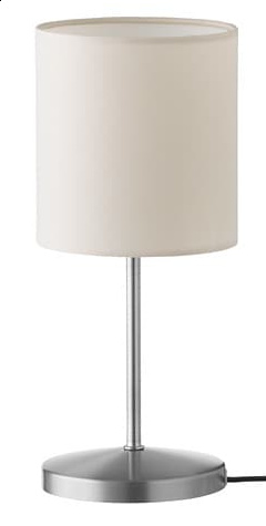
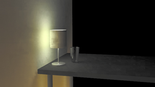
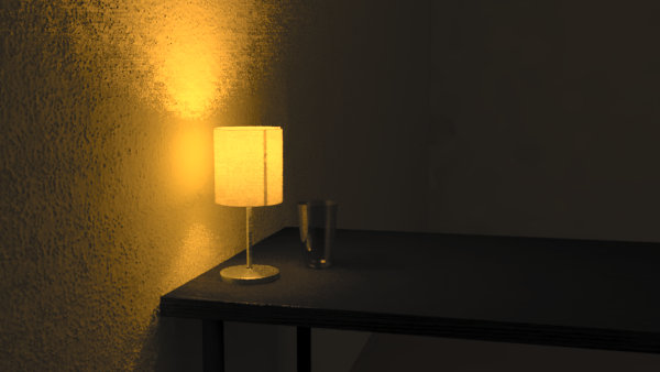
I am looking to simulate my workdesk as a training exercise. It is a black wooden desk from the Ikea budget range :slight_smile: On top it has a budget Ikea lamp, that looks like this.

2018-08-25-185139_240x475_scrot

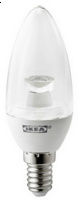
Of particular interest is that the lamp shade is made out of a translucent fabric. The next complexity is that it holds an Ikea LED chandlier bulb, like this one. It is clear, and has an LED reflector inside with a very funky shape.

2018-08-25-190056_78x202_scrot

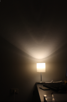
On my desk, the combination makes for a fascinating lightshow.

2018-08-25-190225_224x340_scrot

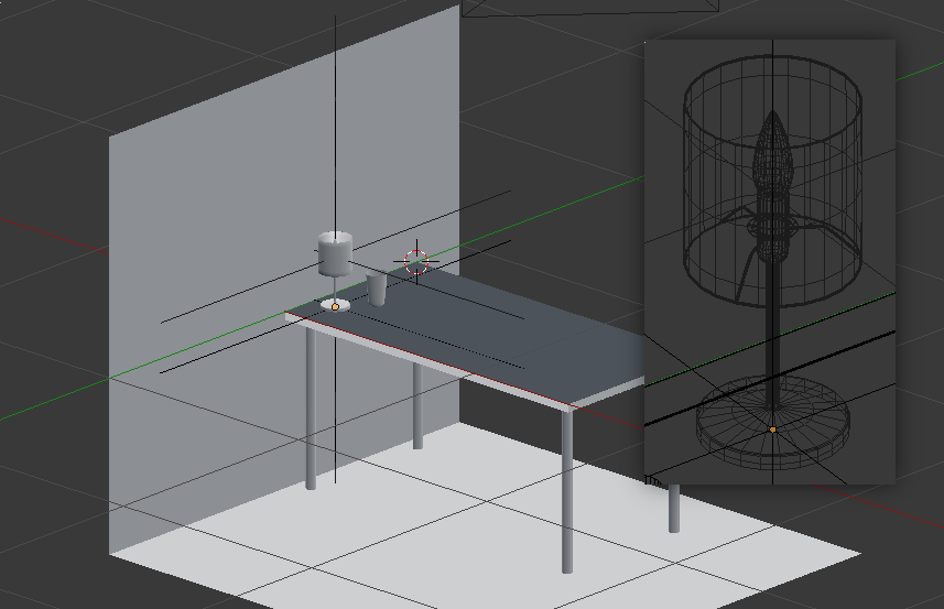
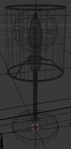
I am attempting to model this setup. Here’s a model, and a wireframe of the lamp itself.

The issue is that Ikea does not provide .ies files or specifications of any kind.

In lieu of an .ies file, I decided to try with simply assigning the bulb with a light material. I used lampcolour as follows below. I picked warm white, as the bulb temperature is 2700K, and in the future I want to add a computer monitor with a white screen. The polygon area is the surface area of the bulb to which I am assigning this material to, and the product says it outputs 200 lumens.

Enter lamp type [WHITE]: warm white
Enter length unit [meter]: 
Enter lamp geometry [polygon]: 
Polygon area [1]: .00365802
Enter total lamp lumens [0]: 200
Lamp color (RGB) = 118.421725 74.188149 23.671471

Here are the material results:

# Macbethcal measurement, specular / roughness unknown
void plastic white_painted_concrete_wall
0
0
5 .93 .96 .74 0 0

# Macbethcal measurement, specular / roughness unknown
void plastic black_acrylic_paint_on_fibreboard_table
0
0
5 .03 .03 .02 0 0

# Totally arbitrary and made up for now.
void plastic white_polystyrene_plastic_inside_and_polyester_outside_lampshade
0
0
5 .7 .7 .7 0 0

# From lampcolor
void light ryet_lightbulb
0
0
3 118.421725 74.188149 23.671471

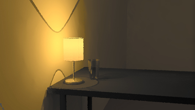
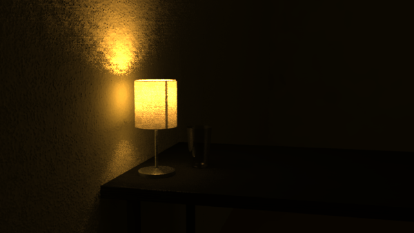
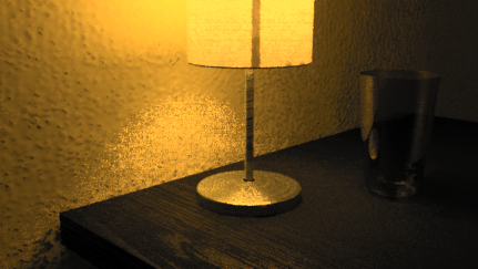
Here’s what renders out. I am viewing this in ximage and have used human exposure settings. The auto exposure is much more saturated.

2018-08-25-192500_609x343_scrot

This is not really what I expected. I do not see the shadow cast by the lampshade, and instead the light seems to be cast directly out of the lampshade onto the wall. Also, for some bizarre reason underneath the table actually seems brighter than to the sides of the table. Why is this occurring?

Also, what can I do to simulate the lamp if no .ies file is provided? The book mentions that for lambertian light sources I can take samples, but this is clearly not a lambertian light source. I think that modeling the internals of the bulb itself is a waste of time, as it would be too inefficient for backwards raytracing to work. Another approach I thought of is to steal an IES file of a similar product, and tweak it for the desired lumen output, and tweak the shape based off photographic studies?

Electric lighting is fun. =) I encourage you to find an .ies file for your light source there. The Radiance light never looks very realistic, especially in the case of something as spiky as a crappy led lamp such as the varietals Ikea sells. Maybe have a look at other lamp catalogs for a similar “candelabra” led lamp that has a clear lens on it, and use that ies file instead. Lampcolor is still useful for determining the proper intensity value to put on your light bulb, and search this forum for posts about lboxcorr et.al for making proper illum-enclosing geometry. Lastly you want to crank up -ds in the rtrace commands to tighten up the distribution. It’s less of an issue for point sources, but this rears its head for linear sources.

Thanks for all your suggestions Rob! I’ve taken all three suggestions and here is where I am right now.

Firstly, I searched everywhere for an .ies file but was unable to find exactly the type I have. I found a few candelabra / candle / chandelier clear LED bulbs, but none of them have the special LED reflector in the centre that casts such spikey shadows as shown in the photo. I had to make do without the special LED reflector (anyway, Ikea doesn’t even sell the special bulb anymore!). Instead, I found this bulb which is similar (clear, 2700K, LED, some elongated, but no fancy reflector).

As the one I found is 315lm, whereas the one I have is only 200lm, I set the multiplier to 0.63 in ies2rad. I hope this is correct. Then, I looked at creating an illum-enclosing geometry. As this .ies is for the bulb, but not the lampshade, the illum should enclose the bulb only, but not the lampshade. I didn’t see the need to create any custom shapes (lboxcorr, or cyl), as I could fit a sphere of radius 0.05 within the lamp. Please see the screenshot below showing the invisible illum sphere enclosing the bulb. This helped a lot with the render.

2018-08-26-235426_1920x1080_scrot

With that in place, I used ies2rad as follows:

ies2rad -t "warm white" -i .05 -m .63 99318.ies

I also cranked up -ds to .02 when rendering.

For the lampshade itself, I have absolutely no idea how to measure the material properties of the lampshade, so I completely made up the material definition below:

void trans white_fabric
0
0
7 .7 .7 .7 .1 .1 1 .0

Result is below (note: stripe on lamp is legit, it’s where the lampshade seam is):

2018-08-26-235408_1920x1080_scrot

So, lots of questions!

  1. How can I measure the lampshade properly? Should I measure the RGB just like any diffuse material with macbethcal? And then perhaps check with a luxmeter how much light there is outside and inside the lampshade? Note that in reality the lampshade is two parts - it’s a polystyrene plastic inside, with a polyester outside. This means that the inside is visually brighter than the outside.
  2. In real life, the circular light / shadow border is caused by the lampshade opening isn’t that crisp - it is a bit blurrier. What could the reason be?
  3. In real life, whereas the circle of light above the lamp (caused by the circular opening in the lampshade) is very visible as shown in both photo and render, the circle of light below the lamp should be very subtle and blurry. In the render, it is quite sharp. Why?
  4. I noticed that I haven’t actually specified 2700K anywhere. Instead I have only specified “warm-white” during ies2rad. In fact, I cheated and used pfilt -t cool-white afterwards to make it look better, otherwise the light would have been far too warm. How do I do colour temperature properly?
  5. Part of what makes the light realistic is the anisotropic specularity of the metallic stand, and in real life the glint is much more pronounced. How can I measure this material property of the stand (galvanised steel with acrylic coating) without fancy equipment? I guess this goes for the table legs too, which is made out of steel with a epoxy/polyester powder coating.

Nice, looking good… So a few quick answers:

  1. Yeah your approach is reasonable. Get the color with your newfound macbethcal techniques, and transmittance by taking a couple of illuminance measurements on the back and front side. This latter bit is prone to wild error, but if you don’t want to sacrifice a lampshade to science, this is probably your best bet. Next best would be to measure illuminance on the inside, and luminance on the exterior, if you have a luminance meter.
  2. That’s probably the ies file’s fault. Probably defined as a super crisp source.
  3. see 2.
  4. lampcolor has a lookup table called lamp.tab that correlates the plaintext options you give to the -t option to actual color temperature and lumen depreciation*.
    You will find this file wherever all your Radiance library files are stored, which is wherever you pointed the RAYPATH environment variable to when you installed Radiance, and you can use these entries as a starting point for your stuff. You could even add to your copy of the file to make things easier if you get a bunch of values you like to use…
  5. More materials measurement fun. Greg has some basic tips for these finishes scattered around in answers on this list, I believe. It’s not my specialty. =/

*From lamp.tab:

# is three real numbers between 0 and 1:  x y and m, where x and y are
# the CIE chromaticity coordinates and m is the lumen depreciation
# factor (multiplier to get mean lumen output from initial lumens).
  • Rob

Thanks Rob, I will buy a lux meter to measure it. However, I think there is more to it. I found another bulb lying around that looks like this. It is a pearl-globe, which means that the source should not be crisp. I found an ies for it here. I used this online converter to convert 2700K to CIE x and y coordinates and added a new value called “2700K” to my lamp.tab. I left the multiplier at .85 in lamp.tab, however, I did specify ies2rad -m 1.02 because the ies file I found was for a 460lm output, whereas the bulb I actually have is 470lm. Here’s my entry:

/2700K/	.460 .411 .85

In real life, with this new pearl globe, it is meant to be much more diffuse, such that if I look at he wall, I cannot see any circular shadow at all (only a very faint blurry shadow if I look carefully). However, in the render, the crisp shadow remains.

In the absence of knowing how to measure this stuff or knowing what values are sensible, I randomly changed the definition of the lampshade to arrive at this result (specifically, I increased tspec, which has the greatest impact on making the lampshade shadow more transparent and I made roughness 0 - any other value will make the lampshade shadow dark like in the previous render):

void trans white_fabric
0
0
7 .7 .7 .7 0 0 1 .6

Result below:

2018-08-28-000924_1920x1080_scrot

This is still incorrect, as you can see there is a shadow cast by the ring (as with a typical lampshade, the polyester fabric is wrapped around a solid ring) at the top and bottom of the lampshade. In real life, this shadow is so blurry and diffuse as to be non-existent. In real life, if I place my hand at the upper opening of the lampshade, the shadow cast by my fingers are also really blurry.

Through my random experiments, changing the specular, roughness, trans, and tspec values in the trans material do not change the fact that the ring at each end casts a sharp shadow. My last suspect is that if I don’t specify -i .05 to ies2rad to create an enclosing illum, I notice that ies2rad creates a sphere with a radius of 0.0005. This tiny size could be the culprit for such sharp shadows, even though I am using the illum object. Is this a sensible guess? Why is the sphere so small, for a pearl globe?

Also, you can see the image colour temperature is very warm. This time, I did not cheat and use pfilt. I am viewing the image with ximage with the DISPLAY_GAMMA environment variable set appropriately for my monitor to check. What am I doing wrong?

This is a fun exercise, I think I’ll join in.

A few things that might help:

  1. Your lampshade has zero reflectance, the indirect bounce off of the inside of the lampshade should contribute to the wall illumination reducing the ring shadow.

  2. What Rob meant about the ies being defined as a super crisp source is that the geometry specified in the ies file is likely defined as a very small sphere (ies geometry is crude, you either get a sphere or a box). However I see you are specifying a radius with the -i flag to ies2rad. Depending on the units of your model, .05 might be really small, check that this roughly matches the size of your bulb.

  3. Once you have a larger bulb you just need to make sure that your render settings are correct and are actually using the geometry. By default all light sources are shadow tested as though they are a point source. The -ds parameter controls source subdivision, since you are interested in very accurate shadows, this should be set to a pretty small number, try .1 and .01 and see the difference.

  4. You may also want to use the -dj parameter. -dj jitters the source rays so they never come from quite the same direction, this will smooth out the striations in the shadows introduced by the -ds approximation. Try -dj .8 or -dj 1

  5. Lastly, you will notice that -dj introduces some noise in your shadows. To reduce this you need to oversample your image by at least 3 times and then use pfilt with both the -m and -r options. the man page has good descriptions of both. setting -ps 1 will also help to reduce noise. If you are using a .rif file -ps and -dj needed to be entered on an rpict= line as they are both overridden by the rad program if you put them on the render= line.

Be sure to post the final results!

Thanks for jumping in too, Stephen! What I actually meant about the light source being defined as super crisp in the ies file is that there’s a seeming sharpness in the candela values that is creating the same or similar hard edges as you see when using the Radiance light primitive. But your catch about the zero reflectance should make a huge difference in smoothings out and softening some of these shadows.

As I’d mentioned previously, the -ds won’t make a huge difference in this case, that is more critical for linear and large area sources.

Lastly, your question about the color temperature. This is why it is recommended that you use WHITE for all your light source specs in ies2rad. Color fidelity in this case is extremely difficult to depict on the display device, and when you have multiple sources of different CCTs in the same Radiance image it gets even hairier, and pcond -h can only do so much. It’s the topic of a masters thesis at least, and Greg is way better at explaining the details and the whys of it all. In short, Radiance is showing you the result of doing all the spectral accounting from pixel to source, but our eyes do a color balance in Real Life that’s not being done here.

Hey Stephen, thanks for all of your suggestions! You’re right, the zero reflectance is likely to be wrong. I’ve increased it to .05 as a guess, as I don’t know how to measure them accurately yet. The -i .05 illum sphere is definitely correct, as the model is in meters, and I double checked by replacing “illum” with “light” and viewing it directly. I already have -ds .02 set, so that isn’t the reason either.

However, you’ve solved it! It turns out it’s the -dj parameter! After increasing it to -dj .8 it now looks exactly like it does in real life! I took your tips about pfilt, and you can see the results below.

2018-08-29-010028_1920x1080_scrot

Edit: here is the exact same render, but with human exposure below.

2018-08-29-083646_1920x1080_scrot

I must say, looking back at it in real life and comparing, it looks really, really close. I think that’s it! I will now focus on adding more details and accuracy in materials. I should probably also mention I bought a luxmeter and took some measurements just above and under the lampshade in full spectrum light. I did this as the sun was setting so I managed to get many readings, and it shows a constant relationship. I used the average gradient as my trans value.

Edit: the book says that for glass, the transmittance value measured needs to be converted to transmission. I did not do any conversion, is this wrong?

2018-08-29-080930_470x255_scrot

Here is my revised lampshade material:

# The fabric weave has many small holes in it.
void brightfunc white_fabric_grain
4 dirt cal/dirt.cal -s .0002
0
1 .2

# Outer polyester RGB measured with Macbethcal
# Overall trans measured with luxmeter
# Inner polystyrene lining is .66 .66 .66, but I don't know how to set a single plane with two materials, one on each side
# Other values are made up
white_fabric_grain trans white_fabric
0
0
7 .66 .67 .59 .05 0 .288 .05

You will probably notice that I have added detail in the texturing. As long as the texture adds to the realism without breaking scientific accuracy, I would like to add as many real life textures as possible.

One of the vital textures to add is the table. The table is a acrylic painted fibreboard top. It is special because it has a cheap wood grain finish, and the wood grain alternates between non-specular and specular. Although I am not experienced enough to accurately measure the specular value yet, I started with a mixpict as follows:

# Average color .5 .5 .5
void colorpict diffuse_map
7 red green blue textures/table_diffuse.pic . frac(Lu)*(1024/901) frac(Lv)
0
0

# Macbethcal .03 .03 .02
diffuse_map plastic shiny
0
0
5 .06 .06 .04 .05 .1

# Macbethcal .03 .03 .02
diffuse_map plastic dull
0
0
5 .06 .06 .04 .01 .1

void mixpict black_acrylic_paint_on_fibreboard
7 shiny dull grey textures/table_specular.pic . frac(Lu)*(1024/901) frac(Lv)
0
0

For the curious, here is the diffuse and specular maps side by side.

2018-08-29-082708_1920x1080_scrot

I also added some anisotropy, and a spiral brushed texture diffuse map to the lamp stand. I copied the new galvanised steel RGB values from the materials.rad file, but in the future when I learn how to measure it I will replace it with something more accurate.

The concrete wall is actually highly textured. It has a concrete stucco finish, with blobs of textured stuff created with a trowel. For the first pass, I sculpted / displaced the wall polygon instead of using any textures, so what you see is modeled. I got the scale wrong, it should be perhaps 10 times smaller, but the effect seems plausible. I need to investigate normal perturbation is more detail.

Here’s a close up render showing the effect of all these textures in play with the light.

2018-08-29-010037_1920x1080_scrot

I still have many questions, but I will start a new thread, as I am now satisfied with the lamp light simulation :slight_smile: Thanks very much everyone! I have learned a lot!

Edit: I have one more question about the lampshade transmittance I added inline above.

1 Like