I would like to create a light source with a special light spread using spotlight and brightfunc in Radiance.
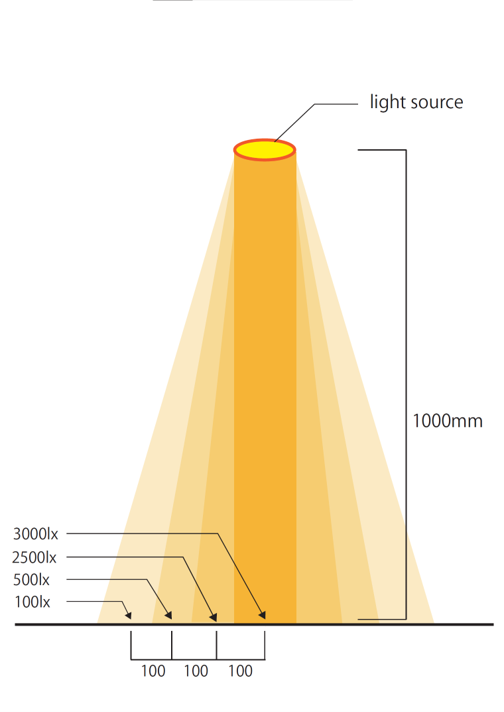
Attached is an image of the light source I would like to create.
Is it possible to change the spread of light irregularly for the light source created with spotlight?
Sorry for my poor English.
It is certainly possible, though one would normally use an IES file and have ies2rad manage the photometry for you.
Do you want the light to change smoothly in the spot, or have hard divisions as you have pictured them? How big do you want the physical spotlight to be, or does it matter? Is your scene description in mm?
I apologize for the lack of information.
I would like to use a spotlight to change the light smoothly. The scene drawing is in mm and the size of the spotlight is supposed to be 70 mm in diameter.
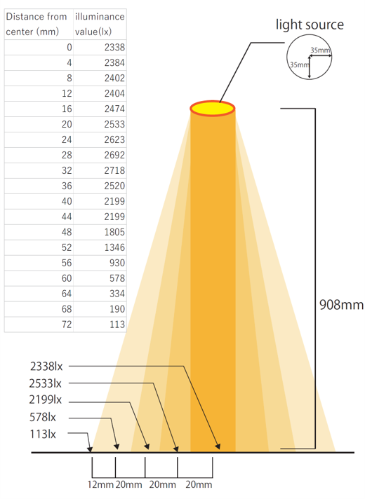
The scene I want to describe is complex, but I have attached a diagram with all the information. I would like to set up the light source so that when the light hits a surface 908 mm away from the spotlight, the light diffuses smoothly from the center to the outside.
The illuminance values that change as you move away from the center by 4 mm toward the outside are shown in the upper left corner of the attached figure. I would like to describe this kind of slightly special distribution in Radiance, is it possible?
Well, I’m not sure how much this will help your understanding, but you can put your data as-is into a file, which I’ll call “horiz_lux.dat” by adding the following few lines for a header:
1
0 0.072 19

2338
2384
2402
...
113
This says you have 1 dimension whose independent axis goes from 0 to 72 mm with 19 data points. I converted to meters just to make all the units consistent. Then, you can reference these data in your Radiance scene file thus:
Finally, you need to define the file “lux_corr.cal” like so:
{ Compute flat source radiance based on horizontal lux measurements }

src_rad = arg(1);   { disk radius in units of data file }
meas_dist = arg(2);  { lux measurement plane distance in units of data file }

Rfactor = 179*PI*sq(src_rad/meas_dist);  { 179 converts lumens to watts }

ang_corr(v) = v / (Rfactor*sq(sq(Rdot)));  { correction factor has cos^4 }

ipos = meas_dist * Sqrt(1/sq(Rdot) - 1);  { distance times tangent of theta }
I checked and this seems to work. Apologies if the reasoning is unclear.
Best,
-Greg
P.S. I made a minor edit/correction to above, realizing factor is actually cos^4.
P.P.S. You can do everything in mm if you prefer – the result should be the same.
Thank you for your detailed reply!
I was able to make the light source I wanted to create. I really appreciate your help. However, I still haven’t caught up with my understanding of what is in lux_corr.cal, so I’m going to do some more thinking on my own.