Falsecolor picture only on selected surfaces

Hi,

I hope to get some help or maybe a hint for a problem I have. I am trying to produce a falsecolor picture. So far I managed to render a picture with all object coloured according to their assignment to the luminance ranges of the falsecolor scale. What I’d like to have instead is a picture where only certain surfaces or objects of the picture are coloured according to the falsecolor palette and the other parts (if its possible) are simply generated as an rpict rendering picture. Will I be able to do something like this?

Thanks,
Ilja

Carsten Bauer created an extremely cool material type in his “Radzilla” project many years ago that did exactly what you are looking for. You assigned his falsecolor material to whatever surfaces you wanted to appear in, well, falsecolor, and rendered as usual. The perfect example was an office space with the room rendered/shaded normally, but the desktops all having falsecolor illuminance maps on them.

Carsten’s public-facing project is long neglected, and I believe he’s taken much of that work to his current employer and perhaps it’s in there somewhere, I really don’t know. Pretty sure he’s with Relux these days.

As to how this might be done in Radiance proper, I suppose you could do two passes–one regular rendering and one falsecolor–and then use pcomb or something to pick out the areas you wanted from the falsecolor and merge them with the regular rendering. That would be rad, actually.

1 Like

Yes, it seems like a great application – I had forgotten that Carsten’s Radzilla had such a function.

The simplest way to do what you want is to create a separate scene with no light sources and all dark surfaces except the ones you want included (e.g., the desktops in Rob’s example). For the falsecolor surfaces, apply the following glow material:

void glow white 0 0 4 1 1 1 0

Run rpict on this modified scene using the same view and dimensions as the normal rendering, outputting to “switch.hdr”. (Other rpict options should be defaults, i.e., no indirect calculation.) Then, use falsecolor with pcomb like so:

falsecolor -lw 0 [other options] -i normal_render.hdr \
| pcomb -e ‘sw=if(gi(3)-.5,1,2)’ -e ‘ro=ri(sw);go=gi(sw);bo=bi(sw)’ - normal_render.hdr switch.hdr > mixed.hdr

Where your desired surfaces are visible (not hidden behind other surfaces), the falsecolor result will show through. Otherwise, you’ll get the original rendering. The only other caveat is that you’ll want your original rendering to be exposed well so that it mixes with the falsecolor output. You may want to pass it through pfilt or pcond for that. (You can replace the “normal_render.hdr” in the pcomb arguments with “!pfilt normal_render.hdr” or “!pcond normal_render.hdr”.)

Finally, you will need to use pcompos with a separate run of falsecolor if you want to put the legend back in. I didn’t want to complicate the directions with those details, which you can hopefully figure out.

Cheers,
-Greg

2 Likes

Dear Greg and Rob,

thank you for the fast response and the helpful advise, I hope I will be able to work something out.

Ilja

P.S. I had a small error in my pcomb command, which I have edited/corrected, above.

Hi,

while the given examples do exactly what was asked for, this may be a nice case to demonstrate how to get more information from rtrace than (ir)radiance.

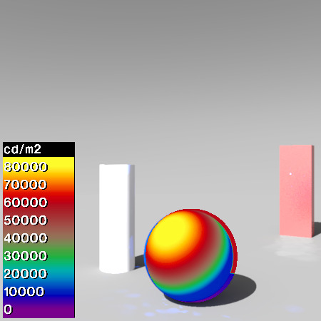
Given an input-file scene.rad, this Makefile renders any object of known identifier as a falsecolor representation of the local illuminance and combines it with a regular (luminance) image of the scene.

# Example how to render selected surfaces in a Radiance scene by a
# falsecolor representation of local illuminance.
# 2022 Lars O. Grobe
# Use at own risk - this may overwrite existing files!

# Surfaces with object name <NAME> will be rendered as falsecolor
NAME="sphereObj"

# View string
VW=-vp 0 -5 2.5 -vd 0 1 0

# Resolution of the rendering, will be scaled to 50%
RES=-x 1600 -y 900

# Upper boundary of the illuminance range for falsecolor
FCMAX=80000

# Resulting image.
# This assumes that the Radiance scene is names accordingly (with .rad extension).

all: scene.hdr

.PHONY: clean

clean:
        rm -f scene.fg scene.bg scene.fc scene.hdr
        rm -f scene.oct scene.txt scene.leg scene.com

scene.leg : %.leg : %.fg
        pcomb -x 1 -y 1 -o $< | \
        falsecolor -s $(FCMAX) > $@

scene.com: %.com : %.fg %.bg %.fc
        pcomb -e 'ro=if(li(1)-1e-6,ri(3),ri(2));' \
              -e 'go=if(li(1)-1e-6,gi(3),gi(2));' \
              -e 'bo=if(li(1)-1e-6,bi(3),bi(2));' \
          -o $^ > $@

scene.hdr : %.hdr : %.com %.leg
        pcompos $(word 1, $^) 0 0 $(word 2, $^) 4 4 > $@

scene.fc : %.fc : %.oct
        vwrays $(VW) $(RES) | \
          rtrace -i -fac `vwrays -d $(RES)` -ab 1 scene.oct | \
          pfilt -x /2 -y /2 -r .7 | \
          falsecolor -lw 0 -s $(FCMAX) > $@

scene.txt: %.txt : %.oct
        vwrays $(VW) $(RES) | \
          rtrace -faa -ab 0 -x 0 -os scene.oct | \
          awk '{a="0.0 0.0 0.0";if($$1=="sphereObj"){a="1.0 1.0 1.0"}; print a;}' > $@

scene.fg : %.fg : %.txt
        pvalue `vwrays -d $(RES) | awk '{print $$1, $$2, $$3, $$4}'` -r -d -h -H $< | \
          pfilt -x /2 -y /2 -r .7 > $@

scene.bg: %.bg : %.oct
        vwrays $(VW) $(RES) | \
          rtrace -fac `vwrays -d $(RES)` -ab 1 scene.oct | \
          pfilt -x /2 -y /2 -r .7 > $@

scene.oct: %.oct : %.rad
        oconv $< > $@

Note the required leading tabs in a Makefile!

Similary, one can select surfaces by modifier, distance, orientation… just by adjusting the evaluated output of rtrace (-os in the scene.txt target). And this does not require any modification of the scene.

This is an example scene with the result:

# all material definitions:

void plastic whiteMat
0
0
5       .9      .9      .9
        0       0

void metal blueMat
0
0
5       0       .1      .8
        .8      .02

void plastic redMat
0
0
5       .5      .1      .1
        .2      .04

void plastic grayMat
0
0
5       .2      .2      .2
        0       0

void trans screenMat
0
0
7       1       1       1
        1       0
        1       1

# a simple box 1m x .6m x 3m
!genbox redMat boxObj 1 .6 3 | xform -rz -30 -t 4 8 0

# a cylinder of diamter 0.8m, 2.4m height
whiteMat cylinder cylObj
0
0
7       -1      4       0
        -1      4       2.4
        .4

# a blue sphere
blueMat sphere sphereObj
0
0
4       .5      2       .8
        .8

# a dark gray ground-plane
grayMat ring groundObj
0
0
8       0       0       0
        0       0       1
        0       24

# a sunny sky
!gensky 3 21 14 +s

skyfunc glow skyGlow
0
0
4       1       1       1
        0

skyGlow source skyObj
0
0
4       0       0       1
        360

scene
Please take this just as an illustration of rtrace’s capabilities and be aware that the commands would overwrite or delete the files

scene.fg scene.bg scene.fc scene.hdr scene.oct scene.txt scene.leg scene.com

if present in the same directory.

Best, Lars.

5 Likes

Lars’ solution is very clever.

If people think this function is valuable, we could probably add an option to falsecolor where you give it an octree and a modifier name (or surface name?) and it generates the corresponding stencil, similar to the way falsecolor mixes -i input.hdr and -p view.hdr pictures with the -cb and -cl options. You might also want to key it based on surface height and/or orientation. It’s a bit tricky to serve every desirable option…

-Greg

1 Like

I think this could be of value

1 Like