Hi list,
I have encountered some problems with the 5 phase method when referring to this tutorial:
Daylighting simulations with Radiance using matrix-based methods
For the first two parts of 3 phase simulation, why we choose ‘glazingvmtx.rad’ rather than ‘glazing.rad’ as the receiver surface for the V matrix and the sender surface for the D matrix? Is it related to the material ‘glow’ ?
In the direct sun coefficient simulation part, what object should replace the ‘blindsWithProxy.rad’ if there is just the double insulating window not the window with blinds?
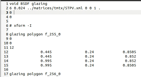
As for the ‘blindsWithProxy.rad’ , the material is BSDF and the geometry is the combination of the glazing and blind. How to make similar file if I have the XML file of the insulating window from the software WINDOW? What about the thickness of the material BSDF? The thickness of the insulating window is 24 mm, is it reasonable to create a file ‘glazing_bsdf.rad’ like this?
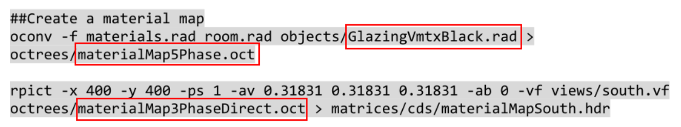
When generating the material map, why we choose ‘GlazingvmtxBlack.rad’ to make the window black? And ‘Map5Phase.oct’ and ‘Map3PhaseDirect.oct’ is not identical, which one is true?
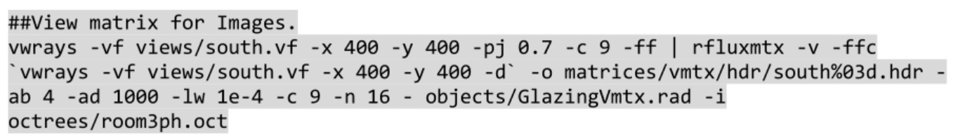
Why we have to get the ‘illuminance sun coefficients for images’ and ‘luminance sun coefficients for images’ respectively and combine them together later by the material map?
Sorry for so many questions, any guidance or advice is much appreciated!
It should be materialMap5Phase.oct and not materialMap3PhaseDirect.oct. These lines in the tutorial script and the corresponding Page 80 of the tutorial reference the incorrect octree.
The rationale for doing so is explained in this paper.
As for the ‘blindsWithProxy.rad’ , the material is BSDF and the geometry is the combination of the glazing and blind. How to make similar file if I have the XML file of the insulating window from the software WINDOW? What about the thickness of the material BSDF? The thickness of the insulating window is 24 mm, is it reasonable to create a file ‘glazing_bsdf.rad’ like this?
Hi Taoning,
The window system is a double-glazed insulating window which consists of semi-transparent photovoltaic laminate. There is not any shade application like blinds. As for this system, I am wondering what kind of file is needed in the place of ‘blindsWithProxy.rad’ for the direct sun coefficient simulation part. I create a similar file ‘glazing_bsdf.rad’ by using the XML file from the software WINDOW:https://drive.google.com/file/d/18JmSoPEoVe9FazEm5QSW8UfNf6CmKj_f/view?usp=sharing
Is it reasonable? The simulation result seems normal.
Hi sarith,
Thanks for your detailed reply!
According to the paper you recommended, the material map should be ‘materialMap5Phase.oct’ where facade is set to black. In that paper, it pointed out that the facade is represented by high resolution BSDF such as ‘To calculate an improved representation of the façade itself that includes the contribution of direct sun on and interreflected within the façade system itself, an additional rendering is performed in a model where the façade is represented by the high detail description (BSDF or geometry) and all other surfaces are set to black.’
I compared the simulation results between the ‘DDS’ workflow and the 5 phase method. I found that more light transmitting through the window by using the ‘glazing_bsdf.rad’ in 5 phase simulation. Could it indicate that ‘glazing_bsdf.rad’ is more accurate?
Hi @lee , those two workflows are not related. With the ‘DDS’ script, I was just trying to replicate (in a limited capacity, without any interpolations for the sun position) the workflow proposed by Bourgeois and Reinhart in their 2008 paper. Before the development of rcontrib and rfluxmtx, there was no “simple” way to perform such simulations. So, back in 2016-17 when I was working on the tutorial, I just thought it would be a good idea to document this workflow using pure Radiance programs ( as opposed to several custom programs like rtrace_dc, rtrace_dc_2305 etc that exist in Daysim).
This looks like some PV stripes going across the window. I am not sure what’s goes on between the stripes. My first thought would be to use something like mixpict/colorpict to model the pattern and use genBSDF to generate a glazing system BSDF with geometry.
It sounded like you used WINDOW to generate a Klems BSDF. You might want to turn on peak extraction (aBSDF) if you can see through the PV and distinguish objects on the other side. Use tensor tree BSDF if not to preserve some luminance intensity.
In general, if you are interested in visual comfort (I assume so since you are using 5-phase), getting the glare source intensity correct is important. Of course, since it’s a novel system, it’ll needs to be checked against some kind of field illuminance and luminance measurements.