【Background】
I am currently a student majoring in architectural light environment at university.
In my research, I have found that there is a difference between “when subjects evaluate the light environment by observing the actual space” and "when subjects evaluate it by presenting a rendered image on a monitor that reproduces the actual space ".
Therefore, in order to reproduce the actual space on the monitor, it is necessary to convert the color to match the output (monitor) in addition to the usual rendering using Radiance.
In the process, I have referred to "Picture Perfect RGB Rendering Using Spectral Prefiltering and Sharp Color Primaries” Witten by W.Greg.
【Our Color conversion STEP】
1.Before rendering
1-1 Measure all the materials in the room with a spectrophotometer under the CIE standard light source (D65)
1-2 Convert the materials to Sharp RGB space and render in Radiance.
2. After rendering
2-1 Convert the rendered image with the color information in Sharp RGB space to the color of the color space (P3-D65) of the monitor
2-2 Simultaneously perform gamma correction to match the monitor settings .
The specific formula is shown below.
【STEP1-2 ,Convert to Sharp RGB color space】
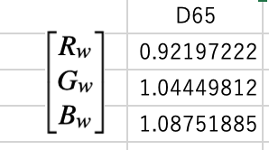
Figure 1. an example of measured XYZ under D65
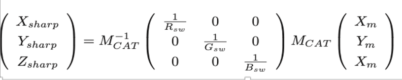

Figure 2. Formula for converting from measured XYZ to sharp XYZ
・Mcat:a transfer matrix (XYZ->RGB), which is same as Mc in" Picture Perfect RGB Rendering Using Spectral Prefiltering and Sharp Color Primaries"
・Mcat^-1 : a transfer matrix (RGB ->XYZ), same as Mcat Inverse
・Rsw Gsw Bsw:Coordinates of the (D65) white point of the light source
・Xsharp Ysharp Zsharp: XYZ values in sharp RGB

Figure 3: Formula for calculating Radiance RGB from Sharp XYZ・
【STEP1-2, Commands for rendering】
・mkpmap -apg ****.gpm 50k -t 10 ****.oct
・rpict -vp 1500 0 1000 -vd 0 500 0 -vv 120 -vh 120 -ap ****.gpm 500 -vu 0 0 1 -ab 1 -aa .1 -ar 4096 -ad 4096 -as 2048 -ds .02 -dc 0.17 -dt 0.05 -dj 0 -pj .5 -ps 1 -dp 2048 -x 800 -y 800 -t 10 > RenderedImage.hdr
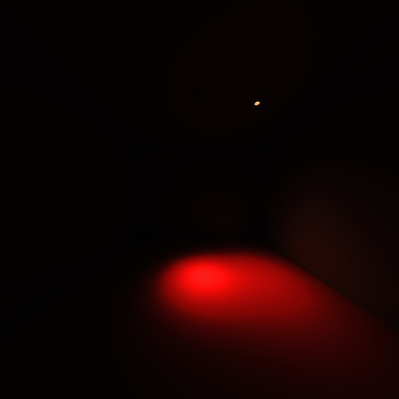
The image created by the procedures in STEP1 is shown here.
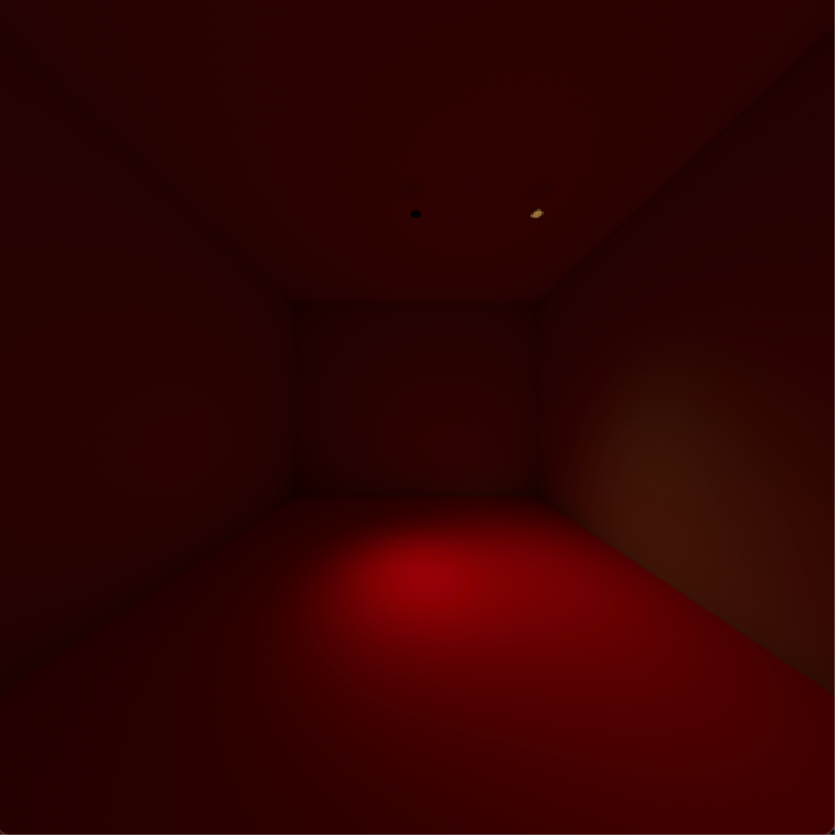
Figure 4. Image after rendering
【STEP2-1/2-2 Color Transformation and Gamma Correction Commands】
pvalue -o -h -H -d RenderedImage.hdr
|rcalc -e ‘$1=(1.5540*$1-0.4456*$2-0.1084*$3)^0.454545; $2=(-0.0080*$1+1.0219*$2-0.0139*$3)^0.454545; $3=(-0.0105*$1-0.0274*$2+1.0377*$3)^0.454545;’
|rcalc -e ‘$1=(0.81563331*$1+0.047154779*$2+0.137216627*$3); $2=(0.379114399*$1+0.576942425*$2+0.04400087*$3); $3=(-0.012260137*$1+0.016743052*$2+0.99551876*$3);’
|pvalue -r -pXYZ -y 800 +x 800 -d -h -H -o |ra_xyze -r -p 0.680 0.320 0.265 0.690 0.150 0.060 0.3127 0.3290> ConvertedImage.hdr
・The coefficient of the first “rcalc” is from Figure 5.6, converting the rendered image to the P3 color space of the display.
・Gamma correction is simultaneously multiplied by (1/2.2 = 0.454545) to match the setting of the monitor.
・The second coefficient of “rcalc” is MC^-1, and XYZ to RGB conversion is performed.
・Since the monitor is in the P3 color space, the (-p 0.680 0.320 0.265 0.690 0.150 0.060 0.3127 0.3290) in “pvalue” uses the primary color of it.
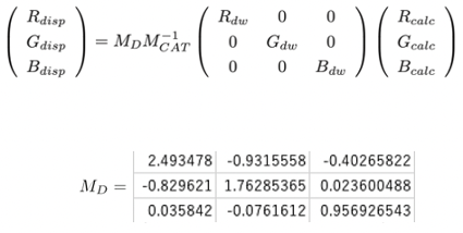
Figure 5. Equation used as a reference when converting to a display color space P3.
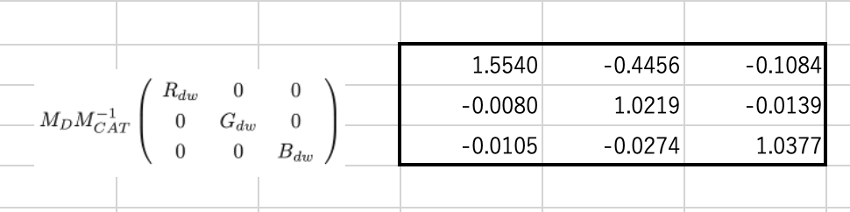
Figure 6. the part of Matrix in Figure 5
・Rdw Gdw Bdw:the RGB coordinates of white point D65
・Rcalc Gcalc Bcalc:RGB per pixel of the image
・Rdisp Gdisp Bdisp:RGB values according to the monitor (display)
・MD:In this case, adjusted to P3 as shown in Figure 5.
Through the color conversion in step 2, I got a converted image (Figure.7) but it is uneven (as shown in Fig8, the discomfort is easier to understand when viewed in False Color.) and has a strong reddish tint, which is far from the actual space.
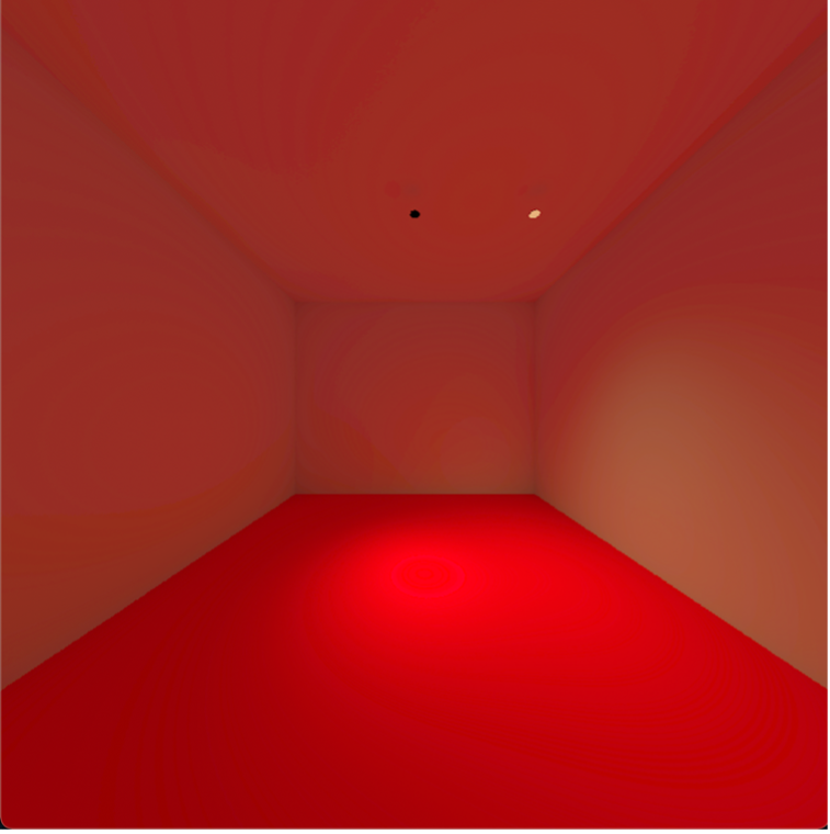
Figure 7. Image after color transformation
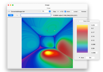
Fig8. A false color of the converted image.
It’s a long story, but my questions are as follows;
- Are the rendering procedures correct?
- What is the reason why the image after conversion is too red?
- What is the cause of the unevenness (wall circle) that appears after color conversion?
- Is the timing of gamma correction correct?
Thank you very much for your time.