Would it be possible to use vwright function to shift a rendered image? I am trying to create a stereoscopic view using 1 rendered image and was wondering if the Radiance software has such a function.
If not, what other alternatives would i have, if i could only work with this 1 image.
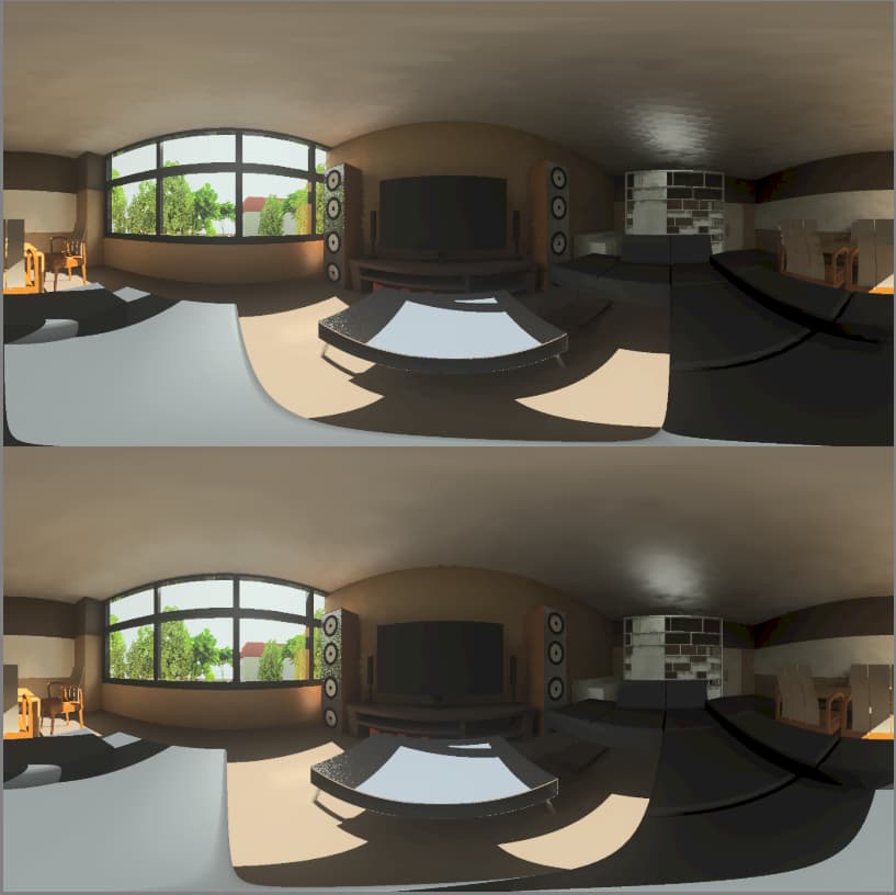
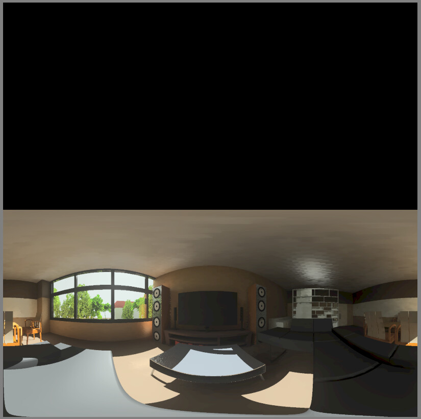
Below i have attached a panoramic image i rendered out for reference.
The vwright command takes a set of Radiance options (or a view file or picture) and shifts it to the right the specified distance (negative for a shift to the left). It does not alter a picture directly – that must be rendered again with the view it generates. However, this may not be what you want for 360° views for VR, like the one you are showing.
Mark Stock write a view360stereo.cal file that generates rays for rtrace to create a stereo 360° azimuth-altitude (“equirectangular”) image suitable for a virtual reality still. This is included in the standard Radiance source distribution in the ray/src/cal/cal directory. The comments at the top explain its use.
For my context, im using climate studio as a Radiance plugin, so perhaps the view360stereo.cal might not be able to be utilised from my side.
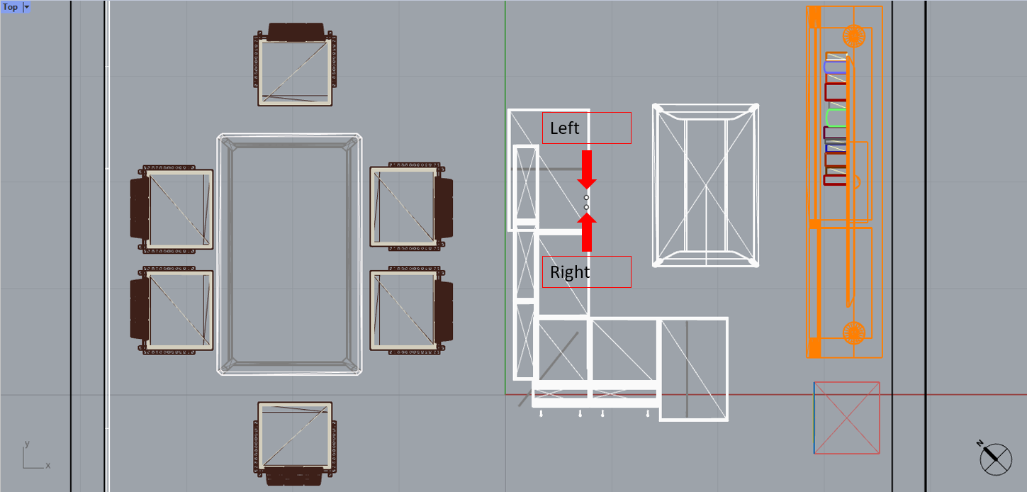
In the case of an equirectangular image, how would I go about to create a stereoscopic view effect? Would it be possible to render two slightly different angle points in my Rhino 7 simulation, as shown in the attached image below to reach the same effect? Apologies as i’m still relatively new to this.
The problem with 360° stereo views is that as you rotate, the view origins (eye positions) also should rotate, and this is what the view360stereo.cal file achieves with rtrace. Without it, you can render normal perspective views, and even fisheye views where the head is in a fixed position, using vwright coupled to rpict (or OpenStudio) as mentioned.
I am currently exploring the function of view360stereo.cal file and would like to ask about the command lines.
For example, to generate an equirectangular image with a resolution of X,Y: 4096, i would input the values below. What default values shall i put for the rpict options? Would it be something like the below commands?
I can’t advise you on the rtrace options, as it depends on your scene. You could try the “rad” program, which takes qualitative metrics and goals and converts them to rendering options. I can give you more pointers on that if you are interested.
Note that the recommended settings for view360stereo.cal assume your world coordinates are in meters. If they are not, then you should apply a conversion from meters for the IPD, EX, and EZ variables. (Since you set EX and EZ to zero, I guess you don’t have to bother for those!)
OK, rad is an “executive” program created to manage compiling scenes, rendering, and filtering the result. There’s a short tutorial on scene creation that features rad at the end of Chapter 1 of “Rendering with Radiance.” There’s also a deeper dive in this little-known presentation. These are older documents, so bear in mind that “rview” was renamed “rvu” to avoid conflicts with the vim editor.
Some good examples of rad input files may be found in the ray/test/renders/ directory in the standard distribution. There are 14 different *.rif examples for creating the render outputs used in regression testing.
However, I am suggesting you use rad not for rendering management, but for one of the subtasks thereof, which is parameter setting. For this, you need to study the information in that little-known tutorial, particularly the pages titled “Rendering Quality” and “Qualitative Scene Information” to help you decide how to set rad’s variables. Then, you can run rad in the following way to create an options file:
rad -n -s myscene.rif OPT=myoptions.txt
This invocation will create a set of options in the named “myoptions.txt” file that looks something like this:
Sorry about the link – I’ve corrected it in my post. Try again.
The .rif file is something you create with your favorite text editor. It isn’t created automatically. As indicated in the man page, some variable settings are required and some are optional. The Chapter 1 tutorial should help.
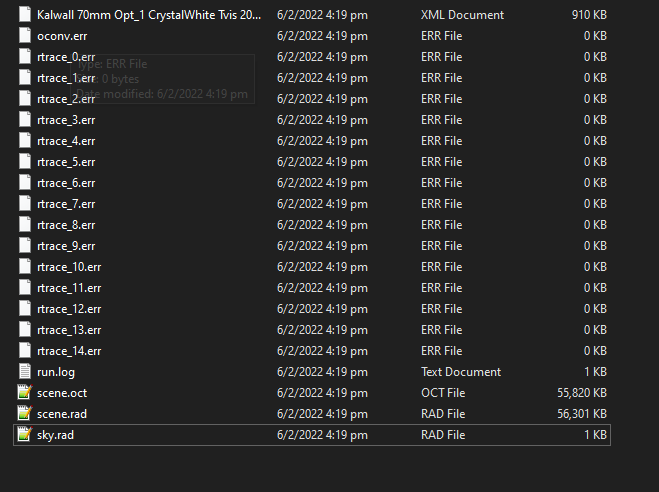
Thanks for your help! I tried generating a model with my scene.oct using the view360stereo.cal file. However, the HDR image that was generated could not be opened with Luminance HDR. Do you happen to know why?
I like to ask as well, with this view360stereo.cal, how long does it render the image, or am i able to set a preset render time like in Climate Studio/DIVA?
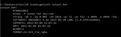
Your command looks OK to me. What does “getinfo output.hdr” report?
I downloaded “Luminance HDR” for the Mac, which I had not tried before. It seemed to open the image I generated using a similar command to yours, so I’m not really sure what could be going wrong. You might get an all-black image if your origin is in the middle of a wall or something, but it should still open.
Oh I see, i guess the issue is probably because of the origin point. Since it was not stated in the commands. Just wondering, for the view360stereo.cal file, how should i input in the commands for a specific point that i want to be in the image? Thanks alot!
Good – your header looks OK. You need to set the X, Y, and Z constants appropriate to where your person is standing in the virtual space. So, if you have a box room going from 0 to 10 in X, from 0 to 5 in Y, and from 0 to 3 in Z, centering the person would give you:
To respond to your earlier question about rendering time, there is no easy way to predict how long it will take other than watching the file grow. Since the ultimate file size in this case will be 409640964 bytes, you can check progress as the process runs with “ls -l output.hdr” from another window (or run your rtrace command in the background).
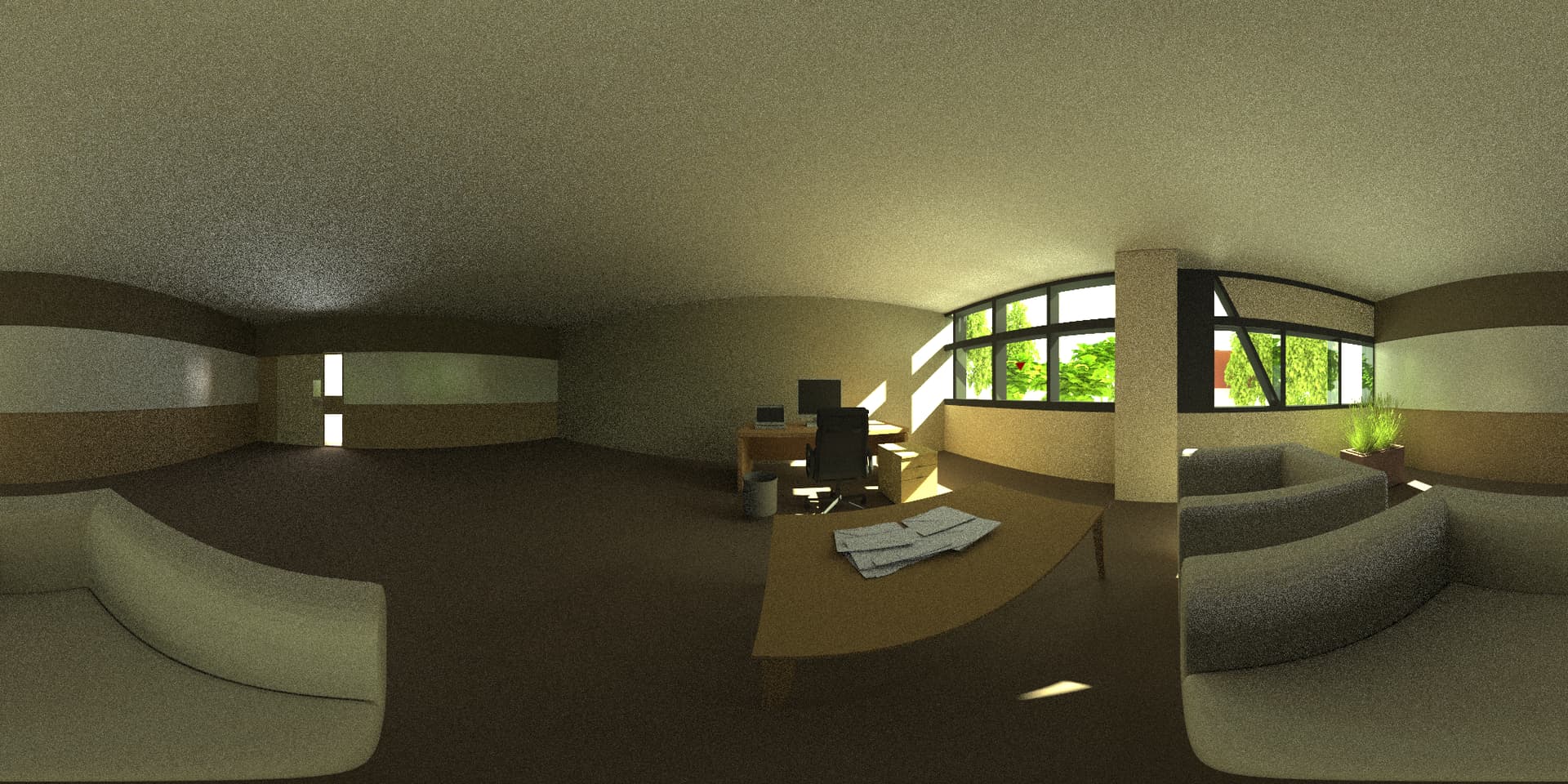
I’m just wondering, what variable do i change to make the output.hdr render as one solid image instead of a top/bottom image? So to say, the image above is split into two seperate images instead of one image.
Glad you got it working! The cal file is designed for particular VR apps, I believe. (I’ve never actually used it, I’m afraid.) Since you’ve already rendered the result, it’s easier to just pull it apart into two images using pcompos:
At least, I think I got that right. (Left eye is upper half, right eye is lower.) Changing the cal file to render left and right independently would be a bit more effort.
 Could you please point me in the right direction!