The simplest is probably putting a spherical light source of an appropriate size slightly below the ceiling plane. If you have a 4x6x3 room in the positive qudrant for instance and Z is your up-direction, you might use:
Yup, I’ve done this already. But then I need to map this material it in the .obj file or give it as an extra one right? This is what I do not understand how to do it.
You don’t need to map it – just add it to the Radiance file(s) you are already rendering with. If you are using obj2mesh, then put the above near the “mesh” primitive that includes it in your scene. See Chapter 1 of Rendering with Radiance for the basics if you don’t know them.
# this is the material for my light source:
void light bright
0
0
3  1000  1000  1000
#  red_emission  green_emission  blue_emission  #

# here is the light source:
bright sphere fixture
0
0
4  2  3  2.8  0.125 # <-- tried to replace these values with 4 45 3 44.8 0.125 see output from getbbox command below
#  xcent  ycent  zcent  radius  #
respectively.
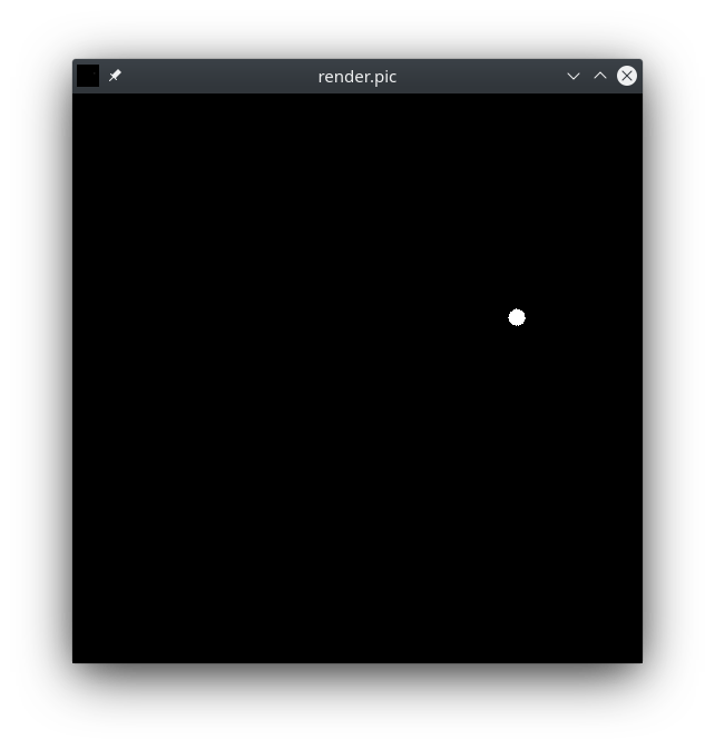
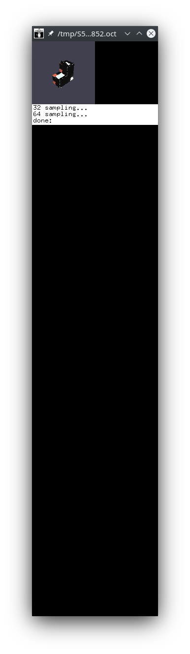
Trying to visualize my mesh with objview gives me the following output:
I can see the mesh on the top left corner but the output window seems a bit strange (I am not sure whether it should look like that though, meaning stretched).
Based on these I tried to play with the position of my light source as well as the camera vp, vd and vu parameters but I couldn’t get any good rendering output.
Are you trying to view your mesh from the inside or the outside? The objview script adds distant lights for you, and should work fine for viewing the house from the exterior. Did you try resizing your window? It looks like it started out way too small for some reason – perhaps to do with your X11 window manager. Maybe someone else has experience with this. I’ve never witnessed that particular problem.
You only need the light source for viewing interior rooms, and you need to know where they are and what size. Do you even know which way is up in this model? It could be the Y-axis is up, where you should render with -vu 0 1 0 and set your source to somewhere around Y=3 to be near the ceiling. You can even create an array of lights using the -a option in xform.
It doesn’t really matter I just wanted to view the mesh with the objview to confirm that my mesh loads correctly. My guess is that this stretched window output is also X11 related, I’ve tried to resize the window but then this output image on the left top corner becomes totally black and moreover while the window resizes this left top corner output seems to be staying fixed.
BTW I am getting a similar view also with rpict and rvu.
That’s why I was trying to get the info with the getbbox command. So I can use it to locate my light sphere but while I changed the values it didn’t really help.
This is most likely the case because if you see the output from the objview is tilted.
Is there a way from the wavefront format to make a better guess about the type of the material to assign for each object other than setting everything to Plastic?
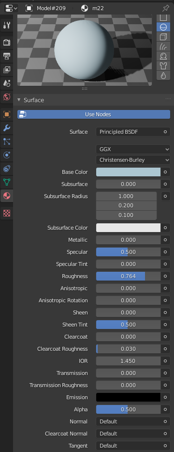
I was checking for example on the Blender material properties once you load a model but it does not seem clear to find the type. See image below (which correspond to a window glass):
I just relied on the object name coming from OBJ, nothing else. I’m not sure how good of an idea it is to “map” OBJ material properties to Radiance materials, as it may lead to incomplete, or inaccurate material definitions in Radiance.
The Blender material properties depends on the engine that is loaded in Blender. Your screenshot shows material data that can be interpreted by Blender’s Cycles engine and Eevee. However, once it gets exported to OBJ, a lot of that data is lost, so unless you plan to map Blender materials to Radiance, it may be better looking at the OBJ output directly. Also note that in Blender materials, there are many ways to define a material, from very simple to very complex definitions. What you’ve shown there is a single shader node, which is relatively simple, but there is also a glass shader node, and many other Blender nodes which can be combined in many ways.
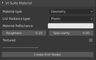
I see, thanks Dion. The idea that I have am trying to implement is to connect these material properties with the corresponding ones of the LiVi tool:
so I was trying to find a way to do the mapping directly in Blender if possible through some definition or node information as you pointed out, which I was aware. I will see if I can manage.